Rudder packing

The friendliest place on the web for anyone who enjoys boating.
If you have answers, please help by responding to the unanswered posts.

kernr

Senior Member
Joined
May 29, 2020
Messages
182
Location
United States
Vessel Name
Serenity
Vessel Make
Grand Banks 47 Europa
Hi All -

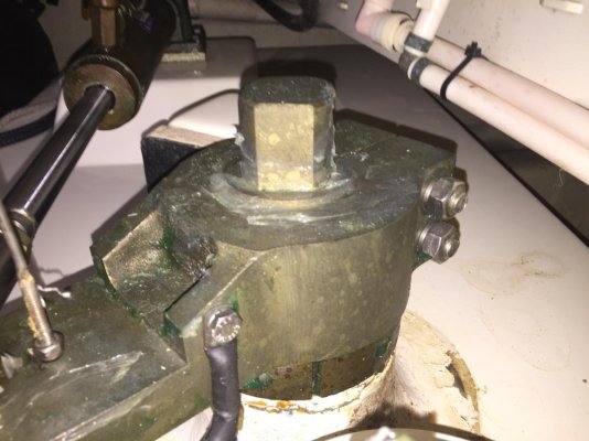
Well I have learned a lot about our GB 47 EU over the past year. One item that I have not checked out though is our rudder posts. A couple of times last year at the higher speeds I noticed water in the bilge of the Lazerette (sp) and I saw the bige pump light come on once or twice while underway. Never an alarming amount of water and never have I observed leakage source while in port or while underway. On this particular boat it seems like the mechanism that secures the rudder posts to the boat is above the waterline except possibly in rough seas or when she is squatting down in the rear. Just never got there at the time it was happening. I have spotted water on the flat surface next to the Starboard post and tried to see any evidence as to its source. So I am guessing I need to look at the packing.

She is on the hard now for about another month and would like any advice as to what needs to get done. Pictures of the port and starboard post are attached. Below the flat surface you see in photos is just fiberglass surrounding the tube that the post comes thru. So where do I start to examine the situation? Do I have it correct to say the packing is most likely under the top bracket with the two bolts clamping it in place and the lower collar is what is securing the rudder post to the top of the tube?

Bob
 

Attachments

  • Port rudder post.jpg
    Port rudder post.jpg
    78.2 KB · Views: 112
  • Starboard rudder post.jpg
    Starboard rudder post.jpg
    86 KB · Views: 79
Rudder Packing

Good Morning all -

Well today I got a set of drawings from GB Malaysia concerning the rudders. They have been extremely helpful in providing meaningful information. Up to this point I have had no answers on the forum which means to me that no one on the forum has had to deal with rudder leakage on the GB 47 rudder configuration.

regardless I do not see any way to pack the rudder post. My read of the drawing is that there is a rudder tiller sitting on top of an upper post bearing. If I were to take the tiller off I believe the post and rudder would be affected by gravity and start downward because I do not see anything to hold it up. So if she starts going down by the stern and the outside water level get to the top of the bearing I believe at least a trickle of water will start entering the lazerette area. I am not terribly concerned about that but I will keep an eye on the posts when in a following sea. I do not see a zerk fitting to put grease on the bearing which would help. I will closely examine to make sure I did not miss something. Also looks to have about 10" of freeboard above DWL to top of rudder post tube. Drawing is attached.

The other interesting thing is that the drawing shows a Delrin Spacer on top of rudder (1.25" tall) just below lower bearing. I do not see that on my boat - hull #50 of the GB 47 EU family. Possibly a change from original GB 47s.

Thanks
Bob
 

Attachments

  • GB47EU RUDDER INSTALLATION (2)[4662].pdf
    144.3 KB · Views: 148
I wish I had something to add. I see 2 "bearings". Upper and a lower. The lower being 4 5/8 inches long. Wonder what that "bearing" is made of? That must be your packing material. I would bet with all of that packing material (if that is what it is) you would have to beat the rudder shaft down to remove it. Is there any side to side play in shaft?
 
To me it looks like the upper bearing has seals, one sealing the bearing to the rudder tube and two sealing the bearing to the shaft. These are the black rectangles in the detail, and that is how seals are often depicted in engineering drawings. If GB is being helpful, I'd ask them for a part number for those seals. If the upper bearing is worn, new seals may not last long and the bearing would need to be replaced for a durable fix.
 
Can you just ask GB if they designed the rudder shafts to be packed and how to do it.
 
I do most of the maintenance on boats because i like to do it. But rudders, thru hulls anything below the water line on the hull I leave to those that do it often.

Now that I think about it I wonder what would be the procedure for packing. I thought the stem is above waterline. Note to self, enquire.
 
The rudder post seals on my 46 are packed with grease. Look for a zirk fitting on them.
 
The rudder post seals on my 46 are packed with grease. Look for a zirk fitting on them.

Thanks. Now that you mention it, I think mine are too. Did not think it was packing as in the prop shaft, Too much in the way, maybe an energetic day pull the covers off and see.
 
Rudder Post

Cigatoo -

Thanks for the response. No there is no side to side movement of the rudder posts.
 
Steve1.0 & Soo-Valley -

Thanks for the responses. I have a good friend up here in the Newport, RI area with a early 2000's GB 46 and I asked him for his configuration and he has a zerk grease fitting on his also. So since I can't find any zerk fitting I am beginning to believe the upper bearing has seals that may be shot - thus a way for water to get in during a rough following sea. More to come. I will ask GB Malaysia more about the design and maintenance.
 
It looks to me that DDW has the right idea. Blow the rudder detail up, a lot, and the bearing and the seals it holds become quite apparent. One seal is between the bearing O.D. and the rudder post/tube. The two others are between the actual rudder shaft and the bearing ID.

It also looks like two screws/bolts are used on top to hold the bearing up in the shaft tube so it cannot slide down and holds a cap in place which is the load support on the top of the rubber shaft tube.

I think from this the boat must be hauled, all the top gear such at the actual steering arm, the steering cylinder and the rudder position must be disconnected and moved out of the way.

Then the rudder dropped and the bearing removed from the tube so the seals can be replaced.

THen the procedure reversed.

I will guess that Delrin is also used here for the seals holder and rudder shaft bearing. Highly wear resistant, tough, and does not absorb a lot of water which can cause swelling of up to 2% if the bearing were Nylon.

While you are at it the addition of a grease fitting may be a worthwhile consideration. Not only would the grease extend the seals life but would also slow any water penetration.

While you are contacting GB it might be worth your while to ask about replacement bearings and seal just in case the bearing has worn enough to require replacement.

I would expect though that if a good machine shop is nearby they should be able to copy the bearing/seals holder of Delrin quite easily.

But carry on with your discussions with GB first.
 
Last edited:
Rudder Post

C lectric -

Thanks for the thoughts. I agree and this morning I sent off an email to GB Malaysia. They will probably not get back to me until early next week. I also asked them about the seals and bearing availability. The boat is currently on the hard and really no problem with the steering but with water in lazerette bilge I will have to face up to this before too long. I also agree with your process flow. I did ask them if the drawing changed prior to my hull #50 build because there is no Delrin Spacer between the rudder and the hull as shown on drawing they provided and I note there is no room for a spacer - maybe 1/4" currently between the top of the rudder and hull and with the rudder post flush on top (see earlier photo) - not sure why you would need a spacer.

thanks
Bob
 
I forgot to mention that there is a bearing, no seals though, at the bottom of the shaft tube.
 
No Delrin Spacer

All -

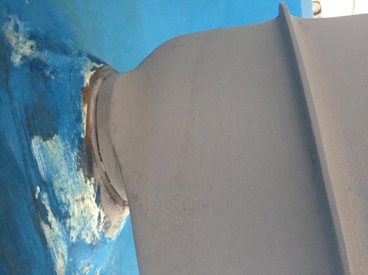
As you can see from the top of the rudder post photo and the photo of the rudder to the hull - there is no space for a spacer on this post. One would need a shaft/post that is at least 1.5" longer. Waiting for response from GB Malaysia.

Bob
 

Attachments

  • Starboard rudder post 2.jpg
    Starboard rudder post 2.jpg
    106.6 KB · Views: 51
  • Port rudder post 3.jpg
    Port rudder post 3.jpg
    96.6 KB · Views: 36
Rudder De4sign

All -

I have not heard back from GB Malaysia yet. I am assuming that one reason is the WE and the other reason is that the drawing and what I have shown from pictures do not match. It is interesting to note that not only is there not a Delrin Spacer between the rudder top and the hull but also the upper end of the post has three pieces shown vs two in the drawing. The drawing shows a bearing with seals and a tiller that is clamped above the bearing. The top of our rudder post has three items - the rudder tiller, then a two piece clamp and then a lip that I have been assuming is the top of the bearing. This may be why there is no spacer on the outside.

Also the drawing states that the top of the post is squared up for a emergency tiller - I am assuming just like many sailboats have. But does anyone have a emergency tiller stored on there boat?

Bob
 
I have an E tiller stored in the flybridge........I think. Still in original packaging? I will have to un wrap and confirm my suspicions. Lol.
 
Looks to be no seals, the seal is going to be a marine grease
Top of post is high enough up above water line DWL that grease is good enough.
Likely at haulouts, you supposed to take it apart, examine the plastic bushings for wear, and regrease it.
If you can add a grease fitting, not a bad idea. I suppose keep pumping it full of MARINE grease (wont dissolve in water like regular grease will or much less) till it starts coming out the top?
 

Attachments

  • rudder bearing.PNG
    rudder bearing.PNG
    84.3 KB · Views: 157
Also the drawing states that the top of the post is squared up for a emergency tiller - I am assuming just like many sailboats have. But does anyone have a emergency tiller stored on there boat?

Bob

Yep, I have one in the lazarette although on a much older 1987 GB42. 4' longer so. Curved/arched. Varnished wood of some variety. I better have someone else onboard telling me where to go and how much because I'm not going to see a thing if I have to use it.

I'm on the hard right now and one of the items I am having done, or so I thought, is rudder racking. Thought it was much like the shafts but maybe not. Anyone with an older GB42 know what I should expect to find? Actual packing or a zirc?
 
I also have a tiller stowed in the lazarette of my 1992 46. It's all heavy gauge galvanized tube, curved/arched. It may be that it is installed extending to port or stb. giving the "tillerman" a view forward from that side. Just a hunch though.
If I get ambitious, I might(read should) figure out which. I still have original cable steering. :-O

I have the original cable steering as well. Stupid me, I didn't really think about installing it to the side.
 
Did you send GB a picture of YOUR installation?
That sure might help them.
You may have to blindly disassemble one of the leaking rudders to see what is on the inside.
Order enough parts, seals and bearings to rebuild the leaking rudder.
I did not see a grease fitting or plug in the picture but then, I can only see one side.
 
Last edited:
Following...

Could you provide the GB contact info please.

My 1999 GB 42 Europa has a similar issue, leaking rudder posts.

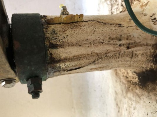
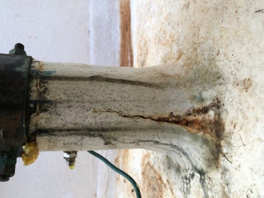
Mine have hairline cracks in the glass which allows water to infiltrate the lazerette at a slow rate. The posts have zerks and when grease is applied it it squirts out the cracks. I’ve installed some hose clamps which has stopped the water leak and I think helps the grease to go where it belongs.

My hull is semi displacement and I think the design does not include the Rudder Shelf as shown in your 47 EU dwg. Mine does not have prop pockets as well. I’m concerned that the rudder post design in my vessel is a significantly weak design symptoms of which are the hair line crack or could have been caused by a grounding.

I could have the posts reglassed but I would prefer to have a better upstanding of the overall design before embarking on a repair.

Sorry about the picture orientations :oops:


Hi All -

Well I have learned a lot about our GB 47 EU over the past year. One item that I have not checked out though is our rudder posts. A couple of times last year at the higher speeds I noticed water in the bilge of the Lazerette (sp) and I saw the bige pump light come on once or twice while underway. Never an alarming amount of water and never have I observed leakage source while in port or while underway. On this particular boat it seems like the mechanism that secures the rudder posts to the boat is above the waterline except possibly in rough seas or when she is squatting down in the rear. Just never got there at the time it was happening. I have spotted water on the flat surface next to the Starboard post and tried to see any evidence as to its source. So I am guessing I need to look at the packing.

She is on the hard now for about another month and would like any advice as to what needs to get done. Pictures of the port and starboard post are attached. Below the flat surface you see in photos is just fiberglass surrounding the tube that the post comes thru. So where do I start to examine the situation? Do I have it correct to say the packing is most likely under the top bracket with the two bolts clamping it in place and the lower collar is what is securing the rudder post to the top of the tube?

Bob
 

Attachments

  • Port post with clamps1.jpg
    Port post with clamps1.jpg
    124.1 KB · Views: 31
  • Port Rudder Post1.jpg
    Port Rudder Post1.jpg
    99.9 KB · Views: 42
  • Starboard Rudder Post1.jpg
    Starboard Rudder Post1.jpg
    125 KB · Views: 30
  • Stbd post with clamps1.jpg
    Stbd post with clamps1.jpg
    114.4 KB · Views: 32
Last edited:
Thanks!

Thanks for posting Nazr’s contact info. He replied within a couple of days with the rudder post dwg for my GB.

Dwg attached in case someone else may need it.
 

Attachments

  • GB 42 Rudder Tube 1.5 inch Dia.pdf
    62 KB · Views: 73
Rudder Posts

Firstbase & Contingensea -

You are both correct - Nazri has been my go to person at GB Malaysia and he has been very prompt in his responses. His last response to me regarding my rudder situation with visuals not matching the drawing was:

Bob
I have forward to my colleague and they will reply shortly.

Meanwhile, there is leak on rudder tube and they suspect the top O-Ring Seal might need replacement.
We don’t keep the spare part and you can contact the maker this rudder tube assemble.

Try to contact Teignbridge at UK. They should be able to assist.

Adrian Evans
Sales Support Engineer
Teignbridge Propellers Int. Ltd.
Tel : + 44 1626 324307
Mobile: +44 7712 063057
Fax : +44 1626 360783
Email : adrianevans@teignbridge.co.uk
Web : www.teignbridge.co.uk

Jade Pinder
Sales Executive
Teignbridge Propellers International Ltd
Tel: +44 1626 324320
Mobile: +44 7702 797 973
Fax: +44 1626 360783
jade.pinder@teignbridge.co.uk

Best regards
Nazri

So I have not yet had a chance to write Teignbridge Company but I will.

Thanks for your inputs,
Bob
 
Rudder Post

All -

So this morning I heard back from Teignbridge Company in the UK - very rapid and pleasant response -see below:

"Hi Bob,

We think that the rudder drawing you’ve been supplied is correct (as per our records), but the installation manual isn’t quite correct – as far as what we have recorded goes.

The rudder tube is sealed with 4 O rings, 1 on the lower bearing and 3 on the upper.

The rudder is held in place by a drop collar which you can see in the photos, it is the slightly rusty looking part directly under the tiller arm with 2 socket head screws in it.

To replace the O Rings, you will need to remove the tiller arm, then support the weight of the rudder before removing the drop collar, once the collar is removed the rudder should be able to be lowered out of the tube.

The bearings are held in place with set screws and once these are removed they should be able to knock the bearings out of the tube.

If you are going to replace the O rings, we would recommend replacing the bearings at the same time.

I hope this helps."

So the drawing of the rudder is attached that they say is correct vs the Installation drawing previously sent out above. They are correct in stating that replacing the bearings at the same time is recommended. I have asked them if they have bearings and seals for this designed assembly and awaiting a response. I do not see the three seals on top bearing and one below on lower bearing they are referring to - I only see upper seals on the Installation drawing. More to come I am sure.

Bob
 

Attachments

  • GB47EU RUDDER BLADE & STOCK.pdf
    84.5 KB · Views: 56
Rudder Post

All -

So, the good news is that Teignbridge Company in the UK can make these bearings and the o-rings that go with them - not without a small fee - quote is attached. Since there is at least a 50 day lead time I will probably get the parts and install at our fall haul out in October. I am sure the process will be an interesting evolution.

Bob
 

Attachments

  • Bearings and Seals for posts 5-11-21.pdf
    174 KB · Views: 74
It also looks like two screws/bolts are used on top to hold the bearing up in the shaft tube so it cannot slide down and holds a cap in place which is the load support on the top of the rubber shaft tube.

I see a step in the bore of the fibreglass shaft tube which would prevent the upper bearing from sliding downwards.

The "cap" - which carries the load of the weight of the rudder/shaft is probably held from rotating by the two screws (or maybe pins).

Nick
 
All -

and the o-rings that go with them

Bob

Strange - the quote lists different O-ring sizes for the inside rings in the top and bottom bearings. This implies that the shaft has a step in it (which does not appear in the drawing). If the shaft is 3.0" diameter at both locations, the 337 O-ring would seem to be the correct one. 335 would appear to be for a 2-3/4" shaft.

These are standard O-ring sizes, available anywhere, depending on the material they are made of. (Buna-N - also called nitrile - is the most common and may well be what they use)

Note that you can change the inside rings without removing the bearings. If the shaft is not loose in the bearings you could consider just changing the O-rings for a parts cost of about $1 each.

The outside O-ring is a static seal (no rubbing) and (I believe) there is no reason to need to change this if the bearing is not disturbed.

(https://www.allorings.com/O-Ring-AS568-Standard-Size-Chart)

Nick
 
Anyone with an older GB42 know what I should expect to find? Actual packing or a zirc?

My 1972 had standard shaft packing glands at the top of the tube. A bitch to get to with twin packing wrenches.
 
Back
Top Bottom