Fuel Tank Design Assistance

The friendliest place on the web for anyone who enjoys boating.
If you have answers, please help by responding to the unanswered posts.

albinalaska

Senior Member
Joined
Jun 6, 2020
Messages
103
Location
USA
Vessel Name
Sea Gypsy
Vessel Make
1979 Albin Trawler 36'
Good Day!

I am in the process of designing new diesel fuel tanks for our vessels main tanks. Our 1979 Albin Trawler is equipped with two ~150gal diesel tanks that are in the worst shape I've seen on any vessel I've worked with. Our vessel also is quipped with two newer(ish) 25gal aux tanks running along the keel in the bilge.

On the lowest part of the forward face on the main tanks there are crusty old gate valves that each feed their own aux tank (aux tanks lead to the fuel filters/engines). Finally there is a fill port on the top farthest aft part of the tanks. There are no vents equipped on the mains. The vents are in the aux tanks. You would have laughed at how long it took for us to refuel bringing the vessel home to Alaska through the Inside Passage last summer... or cried.

These tanks have to go. They aren't bonded, there is rusty metal material flaking off and severe corrosion anywhere the chipped paint reveals.

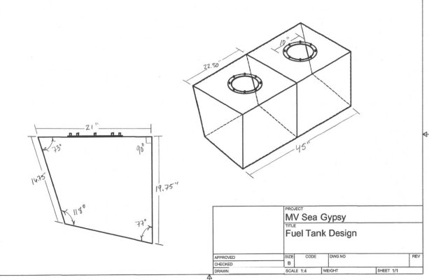
I have found a reputable company in Seattle to design the tanks based on a CAD drawing I was able to whip up (I'm no expert but I think it'll get the idea across) there are very specific angles and measurements so it required some leg work on my part.

We have settled on 316L SS and are satisfied that will give us many years of service but I'm curious about some design concepts if I can soundboard the hive mind here and get some advice?

The 150gal tanks are too large to remove intact. They'll need to be clawed out of the engine room. The idea is that we would replace the two tanks with four smaller tanks (x4 75gal tanks) that are ported together (port and stbd respectively) with a 1" pipe fitting. These smaller tanks would give us the best chance at sparing the removal of the entire cabin floor.

You can check out the photos attached but the pickup would be near the back of the forward tanks so as to decrease the line run to the engines they'll be suppling.

The fill port would be on the outboard side of the aft tank where the rest of the pickups to various fittings would be located. The SAE sensor gauge would be somewhere near the middle/front of the forward most tank. Finally our idea is to include 8" access ports on the topside of each tank (Two per tank) between each baffle to allow access and cleaning when the time comes.

Does anyone see any inherent flaws with this design concept? We are within spec for the baffles based on length and tank and from what I gather this is a fairly straight forward design. The company said there they just completed something very similar to this concept and said tanks come in many different shapes and sizes and pickup varieties with regards to tube placements base on each vessels need. While that is relieving in a way it's vague enough to have me wondering if I'm not missing something.

Could I not just put a single ball-valve fitting on the bottom vertical edge of the tanks and have those supply a manifold and spare all of the pickup tubes in the back of the aft tank? A manifold would be serviceable whereas there isn't enough clearance on top of the tank to pull the pickup tubes once installed.

Secondly - I'm sure this will receive some flak but - I've seen access hatches on the sides of tanks. Since we wouldn't be able to access any hatch on top of the tank would it be preferred to put the 8" hatch on the side of each tank and monitor for leaks? My instinct is that it's just asking for trouble down the line. But I've seen it and very diligent about maintenance.

Anyways - Long message but I would greatly appreciate any feedback or criticisms about this design.

Kyle
mvseagypsy@gmail.com
IG: @MV_SeaGypsy

Pictures show solo tank design and then some more general snapshots of the both tanks in sequence. They would be angled appropriately to the hull for the respective sides. Pics are stbd side.
 

Attachments

  • Screen Shot 2020-11-23 at 2.07.00 PM.jpg
    Screen Shot 2020-11-23 at 2.07.00 PM.jpg
    59.7 KB · Views: 49
  • Screen Shot 2020-11-23 at 2.19.19 PM.jpg
    Screen Shot 2020-11-23 at 2.19.19 PM.jpg
    36.1 KB · Views: 54
  • Screen Shot 2020-11-23 at 2.16.26 PM.jpg
    Screen Shot 2020-11-23 at 2.16.26 PM.jpg
    42.4 KB · Views: 52
  • Screen Shot 2020-11-23 at 2.17.57 PM.png
    Screen Shot 2020-11-23 at 2.17.57 PM.png
    29.4 KB · Views: 46
  • Screen Shot 2021-02-25 at 3.16.28 PM.jpg
    Screen Shot 2021-02-25 at 3.16.28 PM.jpg
    60.3 KB · Views: 59
Last edited:
I am not an expert on welding but I would go with aluminum tanks instead of S/S. I would just go with a bit thicker aluminum than necessary so they will last longer. There is no problem with inspection port in the side of a tank. Installed properly they will not leak. Good luck.
 
Couple suggestions.

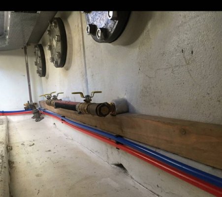
First, to get the tanks to mate together, consider a cutout in thr lower corner for the pipe connection. Tank is pretty shallow here due to curvature of hull so very little lost. And tank install is more robust.

Second, I went with a crossover in front of the tanks. They need to be protected, but they are serviceable and I can drain off some diesel if desired. I found some compact t-handle ball valves.

Peter Screenshot_20210225-191157.jpegScreenshot_20210225-191108.jpeg
 
You might want to check the angles in your drawing -- they are a couple degrees short of adding up to the 360 degrees required to close. It would be redundant, but putting a measurement along the bottom would also help to assure that your other measurements are correct.

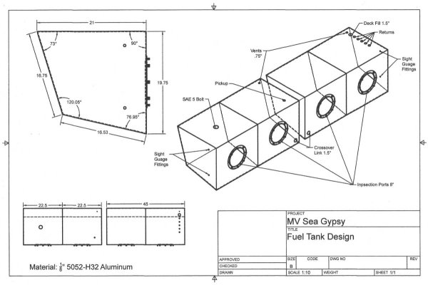
By my calculations, the angle in the lower-left corner should be 120 (if the 73 degree measurement, and the other dimensions, are correct), and the length along the bottom is 16.53"
 
Last edited:
Inspection ports on the side is not an issue for diesel. Would not be advised for gas use. I agree with MVweebles about putting the connecting/crossover valves and tubes on the front side. This will save you many headaches during installation and in the future.

I would also consider adding sight tubes. I have found sight tubes to be very beneficial when trying to gauge my true fuel situation.

Aluminum is much lighter and cheaper. Costal Tanks out of Bellingham is a good resource for Aluminum vs Stainless. They make tanks for both the Dairy and the Boating industry. They are well versed on fuel tank regulations. They also use a machine welding robot to maintain high quality welding standards.
 
A crud sump and a drainage point /ball valve in it
Sight tubes and ports in the front face as mentioned
 
Hi Albinalaska,

I feel your pain, as I've been there on multiple boats in my past. And I'm VERY hesitant to chime in here, as this subject is (obviously) VERY IMPORTANT, very complicated to get right, and not typically a DIY job. Having said that, here's some suggestions:

a. Coastline Equipment in Bellingham (https://coastlinemarinetanks.com/) are your friends. They are most assuredly the premier fuel tank manufacturer in the PNW. They have oceans of experience in not only the fabrication, but the design of tankage as well.
b. 316L is fine material for water tanks. But 5000-series fuel tanks will cost ~1/4 as much, last just as long (assuming they're properly installed), and will weigh 1/2 as much.
c. Pay attention to the method of plumbing your tankage pairs. Your sketch shows what looks like a simple pipe nipple between the two tanks. Don't forget you can't make up a pipe nipple with the tanks down in the engine room! You would have to rotate one tank or the other 360 deg. to make that connection. Your only option, should you desire to mate the tank pairs end-to-end is a pipe union. And, unless you want to add multiple deck fills and vents, your union(s) should be sized AT LEAST as big as the deck fill diameter. So...that's something like a 1 1/2 to 2 in diameter union. Which will require something in excess of 8 inches between the tanks to install and make up. This will adversely affect your available tank volumes.
d. 6"-8" Side inspection plates are highly recommended, on EACH tank, in way of EACH baffled area.
e. Don't forget a vent of each tank is necessary.
f. If you already have two tank fill ports on deck, and two vents, then each tank pair can be combined for both fill and vent.
g. I see little need for a crossover port-to-starboard. You can add a crossover on the fuel drain manifold, if you really feel the need. But below the tank tops (IMHO) is simply not necessary.
h. Sumps on each tank are nice to have, although difficult to accomplish in practice. Ideally, the fuel drains should be in the sumps, but again, tough to do in practice for ganged-together fuel tanks.
i. Another vote for sight gauges.
j. Installation of the new tanks is everything. And the devil's in the details.
k. Steve D'Antonio (https://stevedmarineconsulting.com/) has been down this road about a gillion times. Suggest you chat him up, and consider engaging him as a consultant.

Design of a new fuel system for a cruising powerboat is a complicated subject, and is very much boat-specific. I would highly suggest you do your due diligence in searching out a boatyard and/or fuel tank design and installation company that has actually done this work, preferably on an identical boat, and can put their boots (and eyes) on the ground in YOUR bilge. Attempting this yourself via the WWW is certainly possible, but not easy, and not for the faint of heart.

Regards,

Pete
 
This is so very helpful and why I value the expertise on this site so very much! Thanks gang!

I’m relieved about the inspection ports on the sides. That is something that makes them actually useful once the tanks are installed.

The linkage between the tanks on the side of the tank is invaluable information! I realized immediately once I saw the pictures how that would greatly decrease the amount of effort in installing the link once it was mentioned.

I think there was some confusion on my part, apologies if so- but I’m not looking to link the tanks port to star board; just on their respective sides.

What I think I meant was can’t I have just one fitting in the tank that goes out to a manifold to divvy out the fuel to various devises rather than installing that all IN the tank?

Appreciate the diameter help for the connection fittings. That makes perfect sense to me being that the fill is 1 1/2 in the first place.

Really- thank you to each and everyone of you!! I’ll woke up another version and reach out to Bellingham and see what they have to say. That’s a great point of aluminum works just as well. I liked the idea of 316L because I drank the Nigel cool aid and read his book about how the water resistance properties is the very reason it also makes a good fuel tank. Especially in dampest part of the planet ?
 
Not linking the tanks and using a manifold works fine. Just remember you need to manage the return Lines and each tank would then need its own filler hose. There will be more opportunity to screw things up as well.

I tend to be anal about redundancy, which means I would plumb for all options but that certainly isn’t required.
 
My Willard 36 carried 400 g total in two 200 g saddle tanks. I had a small leak and as part of my refit decided to replace tanks with four 100 g tanks. I chose fiberglass over aluminum because price was about the same. Fiberglass is much more labor intensive and since work is in Mexico, labor is less expensive. I also used fiberglass fittings sourced from a company that supplies them for oilfield fracking rigs. Not cheap, but glassed in with no exposed fasteners. Even the inspection ports go into blind bolts vs thru-bolted into interior of tank.

Had I not had access to inexpensive labor, I would have gone aluminum. I forget the right alloy, but don't cut corners on the alloy or the thickness (given you were considering 316 SS, doesn't sound like your style anyway). The wrong aluminum alloy is more or less an Alka Seltzer tablet in slow motion.

Peter
 
"Forever" tanks would require Monel, although plastic tanks come close and tho more complex to install would be far cheaper.

Either steel or aluminum require mounting that does not keep the tank sitting in water , and allows a deck leak to drain from the top.

A deep sump is key to being able to collect water from the fuel to keep bugs from creating deposits that can clog filters.

Have you measured out to see if cylindrical tanks could be used?

These are inexpensive , heavy wall and can sometimes fit easily , although some volume (not that much) will be lost.
 
Thanks for the input. Here is the second version. I've since had the chance to do some research from recommended sources and have learned that the polishing pickups should be as low as physically possible and as opposite as possible to the polishing returns so this will have to be updated.

Also - any need for sight tubes on both tanks? Seemed helpful to monitor both tanks status for possible blockages within the crossover fitting (assuming issues wouldn't present themselves otherwise first).
 

Attachments

  • MV Sea Gypsy Tanks v2.0.jpg
    MV Sea Gypsy Tanks v2.0.jpg
    93.6 KB · Views: 54
Last edited:
After checking through my emails I discovered that I was already talking with Coastal Equipment in Bellingham. I've also reached out to Steve to see about consulting on further design specifics.

Kyle
 
Lots of great advice. Looking at your plans, I'd expect a single fuel return port. As tiltrider mentioned, a manifold is needed to switch returns between P and S.

Also the top port for a sight tube should be thought of as a vent - you need unpressurized air above the top of the fuel. So probably a port on the top of the tank better supports the sight tube. One sight tube would do for both tanks.

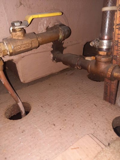
My tanks have a box sump at the end. If you've got the clearance its a great feature. You could have it in one tank to draw from for polishing/draining, and it also gets the sight tube low enough to measure low tank levels.

In this picture the fuel draw is the top fitting, and the bottom one is from the sump.20210226_211538.jpeg
 
Thank you Jeff and Peter - So a sump would just be a box at the lowest point in the tank where the fitting could be placed (like you said) for the polishing system and the bottom end of the sight tube? The top fitting of the sight tube would actually be best placed on the top of the tank to allow unpressurized air? My thought was that I would just tell the people at Coastal that I just wanted sight tubes and they would take care of the rest.

Is there any reason I would need sumps on both tanks? And if the polishing systems job was to polish the cruddy sediment would the send and return be best placed in respective sumps on opposite ends of the set of tanks? Fore and Aft?

Regarding a manifold - Can I just have one send that goes to a manifold to divvy out the rest of fuel needs (I have a Dickinson heater and a Ford Lehman 120 so far - looking into a Proheat x30 hydronic heater soon as well but those are it) and then have 1 return and spare the inherent issues with trying to tighten and maintain 7 return lines at the top of the tank? Or are separate returns and sends essential to make sure nothing suffocates from lack of fuel?
 
WRT manifolds, typically you'd have a single draw and a single return P&S, with a manifold that switches which tank you are drawing from and distributes it to the consumers.

You've already said you want to maintain tank independence. That means you need a similar manifold for the return lines to ensure that you're never inadvertently drawing from one side and returning to the other. You can't have any returns connected directly to the tank.

WRT sumps, one per tank is ideal, but one per side is better than none. If I had one I'd want the fuel pickup to be in the same tank.
 
What’s WRT?

So I’m clear- I do want the tanks port and starboard to be independent except for maybe an emergency valve I can open. Side note: our stbd tank gate valve is stuck closed which we found out trying to refuel in Canada clearing customs (never mentioned by the previous owner!!!) So both of our engines currently draw from the port tank. We would hand pump fuel out of the stbd tank into jugs to balance the list at the end of each day so I’m willing to do whatever it takes to make this thing right.

I’ve read that the pickup for the polisher should be as far away as possible from the polisher return so as to cycle the most fuel possible between the two tanks- but you’re recommending the pickup to the engines be located in the same tank as the sump? Aka- same tanks for the pickup and return? Because of the return of the polished fuel I assume?
 
Last edited:
WRT is with regards to. Sorry for using obscure text speak.

My concern was mostly with water removal. Having a sump makes this easy and practical, as others pointed out. I don't have any hands on experience with polishing systems.
 
I appreciate that - haha -

Well the system right now has no sump so I will gladly check the clearance area below the tank and talk to Coastal Equipment about putting one or two in.


Any idea how large it's supposed to be? Or just whatever I can make it without it rubbing against the hull during vibrations while underway?
 
Last edited:
Right. If you have space underneath and access on the end you won't regret designing it in. Details on how it is used can be changed easily.

My reasoning for having the fuel pickup in the same tank as the sump is that it offers greater protection against picking up water, assuming you're draining/sampling/polishing from that sump.
 
The hassle with site tubes is it requires one to enter the Hell Hole to monitor the reading.

Great in 1900 with paid crew in the engine space, but today it can be way easier .

And other fluids can be monitored .,,,,NOT electric so seldom fails.

Tank Tender

tanktender.com

The original precision tank measuring system. One instrument measures from 1 to 10 tanks. It gauges the liquid level in water, diesel & holding tanks.‎Installation & Operation · ‎Pricing / Order Form · ‎About · ‎Pressure Checking
 
Last edited:
After checking through my emails I discovered that I was already talking with Coastal Equipment in Bellingham. I've also reached out to Steve to see about consulting on further design specifics.

Kyle

If you put a way to bolt the two tanks together, this will make them one unit in place, and remove any torsional stress on the piping. Having them weld a tab on the mating edges would do that.

Ask a pro about side hatches on tanks. ABYC says no side hatches, even though that rules out hatches if the tanks go to the ceiling.
If you go with any metal, make sure to allow for good drainage (and airflow) underneath the tanks.
Are you sure about the abyc requirement of no side ports on a diesel tank? In designing my tanks, I consulted a well known ABYC engineer and he informed they were not just permitted by abyc, but strongly recommended by him.

I also asked about how to join the two side tanks since I thought bottom draw was a no-no. He advised it was permissible for diesel, but the valves should be well protected from impact or step. So that's what I went with.

Peter
 
Good Day!

I am in the process of designing new diesel fuel tanks for our vessels main tanks. Our 1979 Albin Trawler is equipped with two ~150gal diesel tanks that are in the worst shape I've seen on any vessel I've worked with. Our vessel also is quipped with two newer(ish) 25gal aux tanks running along the keel in the bilge.

On the lowest part of the forward face on the main tanks there are crusty old gate valves that each feed their own aux tank (aux tanks lead to the fuel filters/engines). Finally there is a fill port on the top farthest aft part of the tanks. There are no vents equipped on the mains. The vents are in the aux tanks. You would have laughed at how long it took for us to refuel bringing the vessel home to Alaska through the Inside Passage last summer... or cried.

These tanks have to go. They aren't bonded, there is rusty metal material flaking off and severe corrosion anywhere the chipped paint reveals.

I have found a reputable company in Seattle to design the tanks based on a CAD drawing I was able to whip up (I'm no expert but I think it'll get the idea across) there are very specific angles and measurements so it required some leg work on my part.

We have settled on 316L SS and are satisfied that will give us many years of service but I'm curious about some design concepts if I can soundboard the hive mind here and get some advice?

The 150gal tanks are too large to remove intact. They'll need to be clawed out of the engine room. The idea is that we would replace the two tanks with four smaller tanks (x4 75gal tanks) that are ported together (port and stbd respectively) with a 1" pipe fitting. These smaller tanks would give us the best chance at sparing the removal of the entire cabin floor.

You can check out the photos attached but the pickup would be near the back of the forward tanks so as to decrease the line run to the engines they'll be suppling.

The fill port would be on the outboard side of the aft tank where the rest of the pickups to various fittings would be located. The SAE sensor gauge would be somewhere near the middle/front of the forward most tank. Finally our idea is to include 8" access ports on the topside of each tank (Two per tank) between each baffle to allow access and cleaning when the time comes.

Does anyone see any inherent flaws with this design concept? We are within spec for the baffles based on length and tank and from what I gather this is a fairly straight forward design. The company said there they just completed something very similar to this concept and said tanks come in many different shapes and sizes and pickup varieties with regards to tube placements base on each vessels need. While that is relieving in a way it's vague enough to have me wondering if I'm not missing something.

Could I not just put a single ball-valve fitting on the bottom vertical edge of the tanks and have those supply a manifold and spare all of the pickup tubes in the back of the aft tank? A manifold would be serviceable whereas there isn't enough clearance on top of the tank to pull the pickup tubes once installed.

Secondly - I'm sure this will receive some flak but - I've seen access hatches on the sides of tanks. Since we wouldn't be able to access any hatch on top of the tank would it be preferred to put the 8" hatch on the side of each tank and monitor for leaks? My instinct is that it's just asking for trouble down the line. But I've seen it and very diligent about maintenance.

Anyways - Long message but I would greatly appreciate any feedback or criticisms about this design.

Kyle
mvseagypsy@gmail.com
IG: @MV_SeaGypsy

Pictures show solo tank design and then some more general snapshots of the both tanks in sequence. They would be angled appropriately to the hull for the respective sides. Pics are stbd side.

Have you ever thought of something like this as an answer to your problem?

https://www.atlltd.com/industries/marine/below-deck-fuel-water-bladders/fuel-bladders

http://atlinc.com/marine.html
 
Last edited:
I’d venture to say that well placed sumps will negate the need for clean out ports.
Put the largest practical fitting in the sump, and then bush it down to your valve size.
This gives an emergency clean out feature should the valve become blocked.
Run a small polishing system off the sump drain, that runs whenever the engine runs, or separately on a timer.
 
bladders are prone to chafing, so whatever space they occupy, needs to be free from sharp edges or anything that can wear a hole in the material. Also, the sides need to be strong enough to handle the weight of the fuel in the bladder.

The good news is that when a bladder leaks, all you need to do is soften the edge where the leak started and install a new bladder, far cheaper than re-tanking a boat.
 
Another vote for tank tender. Especially of those of us with older boats without N2K networks to take advantage of newer technologies.

Beyond being a great product requiring no electricity the customer support is outstanding. I recently received my order for a seven tank monitor. Tank Tender custom builds each monitor so I was able to get all four fuel tanks on the top row, two potable water and black water on the bottom row. A configuration that make sense to me.
The hassle with site tubes is it requires one to enter the Hell Hole to monitor the reading.

Great in 1900 with paid crew in the engine space, but today it can be way easier .

And other fluids can be monitored .,,,,NOT electric so seldom fails.

Tank Tender

tanktender.com

The original precision tank measuring system. One instrument measures from 1 to 10 tanks. It gauges the liquid level in water, diesel & holding tanks.‎Installation & Operation · ‎Pricing / Order Form · ‎About · ‎Pressure Checking
 
Good Day!

I am in the process of designing new diesel fuel tanks for our vessels main tanks. Our 1979 Albin Trawler is equipped with two ~150gal diesel tanks that are in the worst shape I've seen on any vessel I've worked with. Our vessel also is quipped with two newer(ish) 25gal aux tanks running along the keel in the bilge.


Kyle
mvseagypsy@gmail.com
IG: @MV_SeaGypsy


Nice thread Kyle ! Nice replies - thanks to the group!

Do let us know how your refit proceeds - please, with photos. I am close behind you in needing to do the same job on a CHB34.

Thanks,
Nick
 

Latest posts

Back
Top Bottom