Best overcurrent protection device for Charles isolation tranformer?

The friendliest place on the web for anyone who enjoys boating.
If you have answers, please help by responding to the unanswered posts.

Pau Hana

Guru
Commercial Member
Joined
Aug 29, 2012
Messages
2,691
Location
Good Ol' US of A!
Vessel Name
Pau Hana
Vessel Make
1989 PT52 Overseas Yachtfisher
Going over the install instructions for my isolation transformer, and wondering what overcurrent protection device (between shorepower inlet and IT) has been used by those who have installed the Charles unit- breaker, ELCI, none, or?

Thanks!
 
Well, since ABYC standards specify a breaker near the shore power inlet although older boats don't often have one, I would install one if you don't have it. Put in a 30A single pole, 50A single pole or 50A double pole depending on what kind of shore power inlet you have.


Blue Seas makes one that will work.


David
 
For boats it is required to break both the hot and neutral on the 120V line. So it requires a 2 pole breaker. This would go between the shore power inlet and the transformer. Preferably as close as possible to the shore power inlet.


Ken
 
The breaker is supposed to be installed within 10’ from the inlet measured along the wiring.
 
Asking, not challenging, but about that breaker within 10’ of the inlet by wire travel. That’s a new wrinkle to me. If the shore power stand is properly wired, and the isolation transformer is properly installed, why would there need to be an additional breaker?
For instance, my 1988 Bayliner 3818 was built with two 30amp inlets just forward of the cockpit. Since I don’t have air conditioning, 30 amps is all I need. The inlets are 15’ from the distribution panel as the wires are run. Are you suggesting that I need to install a double pole breaker in that system? My plan is to disconnect one of the inlets, add a new inlet on the transom then use an automatic transfer switch to open the unused inlet when the other closes and combine the two panel wires so the transfer switch acts as a Y cable. I want to do this correctly, but it seems like the configuration would be GFI at the dock, outlet, cord, inlet, GFI, transfer switch, isolator, panel rotary selector, buss breaker, circuit breaker, load.
Have I got this right?
 
Essentially, the breaker at the pedestal is considered iffy, at best.

The requirement for a breaker within 10' of the shore power inlet, measured along the conductor has been in the ABYC Standard for at least 10 years. About 5 years ago, the requirement was for an ELCI to be installed within 10' of the shore power inlet, unless there is an isolation transformer in the circuit.
 
The breaker within 10’ is there to protect the wiring and the boat in case of a short in the wiring. It is an arbitrary distance but you have to pick a distance and 10’ is it.
 
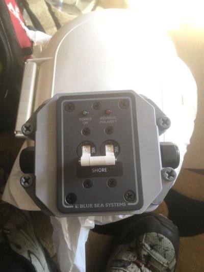
I installed a Blue Seas 2-pole breaker with my Charles isolation transformer. Works fine. I'm within the 10 ft limit.
 
The breaker on the power pole is to protect the power pole , and the wire to the boat and the plug and socket on the boat.

An internal breaker is to protect the wire to the first user a transformer or panel to feed the rest of the boat.

The CB in the panel is to protect the feed wiring to the multiple users on the circuit.

A fuse or CB protects each individual user on the feed wire..

This is how I understand the usual recommendations.
 
I installed a Blue Seas 2-pole breaker with my Charles isolation transformer. Works fine. I'm within the 10 ft limit.

Ditto. I was able to get a two-pole, 50-amp breaker within two or three feet of the shore power inlet.
 

Attachments

  • 5D341B4E-8EE7-4710-8527-79A83E6121E5.jpg
    5D341B4E-8EE7-4710-8527-79A83E6121E5.jpg
    131 KB · Views: 107
For boats it is required to break both the hot and neutral on the 120V line. So it requires a 2 pole breaker. This would go between the shore power inlet and the transformer. Preferably as close as possible to the shore power inlet.

Ken

Ken, do you mean this to apply for boats without an isolation transformer? With my Charles IsoBoost, the neutral shore power conductor is terminated at the boat’s inlet and does not come aboard. The two-pole breaker handles the dual hot conductors.
 
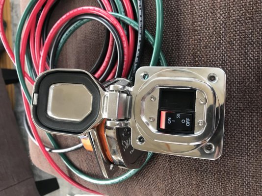
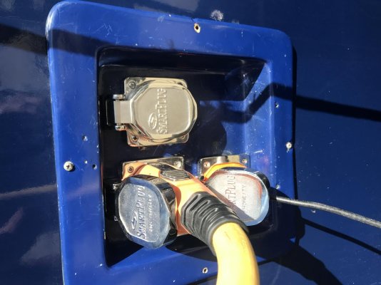
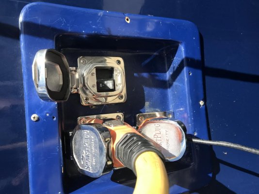
As I’m going from 2 30A inlets to a 50/250 (split to feed both panels), as part of the isolation transformer install, I found that SmartPlug makes a 50A breaker that (conveniently enough) will fill the hole left by the 2nd 30A breaker.
 

Attachments

  • 0BC1C43A-5E8D-47D7-B0D3-450E928F79AE.jpg
    0BC1C43A-5E8D-47D7-B0D3-450E928F79AE.jpg
    199.3 KB · Views: 85
Essentially, the breaker at the pedestal is considered iffy, at best.

The requirement for a breaker within 10' of the shore power inlet, measured along the conductor has been in the ABYC Standard for at least 10 years. About 5 years ago, the requirement was for an ELCI to be installed within 10' of the shore power inlet, unless there is an isolation transformer in the circuit.


If there's an ELCI, what purpose would an isolation transfomer serve?

Full disclosure: I've been wondering whether we need an isolation transformer, or a galvanic isolator... or now, an ELCI... and if so, which... and why.

-Chris
 
Ranger42C:
I think you misunderstood my post: An isolation transformer negates the requirement for an ELCI. An isolation transformer installation still requires a circuit breaker that breaks all current carrying conductors installed on the primary side if the isolation transformer is >10' from the shore power inlet.

That said, if it was my boat, I would install an appropriate circuit breaker on the primary side of the isolation transformer regardless of its distance from the shore power inlet. I just do not trust pedestal circuit breakers.

As to your larger question:
# An isolation transformer separates the vessel's electrical system from the land based mains.

For 240/120VAC split phase the hot (line) conductors are brought aboard with the safety ground wire. The hots are connected to the primary winding and the safety ground is tied to the electrostatic shield located between the primary and secondary windings.

For 120VAC shore power, all three conductors are brought aboard, and the hot and neutral feed the primary side of the xfmr and the safety ground is tied to the electrostatic shield. The neutral (if needed) and safety ground are derived on the secondary side of the xfmr. Total electrical isolation.

# A galvanic isolator is placed in the safety ground wire aboard the vessel. It is recommended to be physically placed close to the shore power inlet so that it is not inadvertently bypassed by a technician or DIY'er later.

The conducting voltage is about 1.2VDC so it will block galvanic current trying to leave or come aboard the vessel via the safety ground (green) wire. It will not block stray current if the associated potential is greater than 1.2VDC and stray current is usually >>1.2VDC.

It will pass AC fault current so that an upstream breaker will trip.

# An ELCI is similar to the GFCI in your bathroom, it just has different trip characteristics. These residual current devices (RCDs) measure the current flowing in on the hot conductor or conductors and compare it to the current flowing back to the source via the neutral. If the two don't match the RCD trips.

For GFCIs, the tripping threshold is 5mAAC. For ELCIs on boats, the tripping threshold is 30mAAC in 100mS. If less current is coming back to the source via the conductors, the current is flowing through the water path. In fresh water that is deadly
Note: The measurement of 240VAC/120VAC split phase is a bit more complicated but the concept is still that the ins must equal the outs within <30mAAC.

This explanation should be reference material- thank you!
 
Ranger42C:
I think you misunderstood my post: An isolation transformer negates the requirement for an ELCI.


Heh... very possible. Thanks for the details; I'm still digesting.

Does an ELCI not negate any "requirement" for an isolation transformer or galvanic isolator?

-Chris
 
Heh... very possible. Thanks for the details; I'm still digesting.

Does an ELCI not negate any "requirement" for an isolation transformer or galvanic isolator?

-Chris

Chris, you can use one of the other:

Isolation transformer:
Iso transformer does exactly that- isolates the boat from shorepower. Think of it this way (this is what helped me to understand the concept)- the shorepower powers the iso transformer, turning the iso transformer into the ship's standalone power supply. Any stray current onboard remains onboard in its own loop. The shorepower cable sees a balance of power fed vs power retuned, and the ELCI on the power pedestal does not trip.

A side benefit is that stray current in the water from another vessel will not attempt to return to ground via your vessel (because you are in an isolated loop) and your anodes will last longer. Ergo- no galvanic isolator needed.

ELCI:
A ELCI onboard the vessel will measure power in vs power out, and if there is leakage of greater than 30 milliamps, it will trip. the next step will be to track down the leakage.

A galvanic isolator can be installed, as it is protecting the vessel from stray current in the water.


Some will correct me if I'm wrong- but this is the way I understand it. Ours goes in this weekend as part of an upgrade from twin 30A to a single 50/250.
 
Last edited:
Put technically, an iso transformer blocks common mode currents. It does very little to differential mode currents.

The long answer from Charlie describes mostly what this means. Blocking a component of lightning surges can also be added.
 
Hmmm... Speak slowly and use small words, guys... I think I understand 90% of the words in Charlie's post, but only maybe 10% of the meaning so far...

Either/or sounds good, especially if one can be significantly less expensive than the other.

Is the main breaker on our boat an ELCI?

Common mode currents? Differential mode currents?

-Chris
 
We could put a customer value to the use of an iso transformer.
Even a grade of A B C F

Here is my assessment.
A means a qualified install of an iso transformer that has a low line tap if its in a 240v system plus a differential surge suppressor.
B is same with no tap. Or no surge system
C only meets an ABYC minimum spec
F does not meet basic safety specs.

Dave,

Your comments are always much appreciated, but would be even more helpful if you could dumb them down a bit for those of us not conversant in geek :D. (Requested by someone who spent a career helping engineers become comprehensible to “normals.”)

Some followups,

-By surge system, are you referring to the “boost” feature in Charles IsoBoost xformers?

-What’s a line tap?

-Does a 120-V “qualified install” without the other gizmos in A, above, also merit an A?

Thanks.

OK, I guess my idea of customer ready isn't. :facepalm:

A "line tap" or "boost" offers the ability to vary the transformer primary to secondary ratio. That is, you can accommodate a 208Volt dock and get 240 and 120 to the boat. Important to avoid hot running motors and other mayhem.
The 120 V only boaters will not need a line tap.
The 240 V only (euro boats) and 240/120 V boaters will, depending on the horribleness of the dock electrical design, enjoy the line tap feature to bring up the High voltage about 10%. If you run around lots of places outside of N. America, make sure the transformer you pick is 50 and 60Hz rated.

"Surge" in this context, is a short term transient caused by lightning. These can range up to 4000 volts in my test world. If this pulse exists on both Line and Neutral verses EARTH, we call that "common mode". If, OTOH, you get the pulse BETWEEN Line and Neutral, we call that "differential mode". The iso transformer virtually eliminates the CM pulse, but will (mostly) allow the DM pulse to get thru. A common MOV surge suppressor helps a lot here, and will be installed after the iso transformer for best effect.

Leakage currents, dock GFCI, ELCB's etc and dock swimmer issues. They won't come from a boat with an iso transformer. Nor will an ISO transformer equipped boat trip out a leakage current device upstream at the dock due to any onboard appliance issue. However, a dock plug/socket issue, cord insulation issue, or even a boat shore power plug/socket issue could trip out an upstream leakage current device, even with an Iso transformer.

Yes, this iron/copper iso transformer is heavy, needs careful mounting, but is otherwise pretty bulletproof. NOT using a iso transformer is a "trust me" concept. It usually works, until it doesn't.

Thanks for the detailed description. I like almost everything about our IsoBoost, except the weight when mounting it. It was described to me as a 235-lb basketball and I had to hire a couple of teenagers to help me with the install. I ended up finding room for a vertical mount on a bulkhead, which has worked perfectly. I do love not having to worry about many of the electrical issues that plague boats.
 
Going over the install instructions for my isolation transformer, and wondering what overcurrent protection device (between shorepower inlet and IT) has been used by those who have installed the Charles unit- breaker, ELCI, none, or?


Thanks!


Back to the original post, I put in a 2 pole circuit breaker inside the boat, within a foot of the shore power inlet.

56184840738__8D04EC9A-DB6E-486B-AA21-342B90D922A8.jpg

Prior to installation at the shore power inlet location inside the boat.
 
Install complete!

The Charles Isolation Transformer is doing its thing to supply power to the boat, and the proper breaker is installed.

We now have a single 50A supplying power to the boat!
 

Attachments

  • 31AEB6C9-73A6-4966-BFAC-63527D7EB7AF.jpg
    31AEB6C9-73A6-4966-BFAC-63527D7EB7AF.jpg
    107 KB · Views: 59
  • 2CC2FAD4-7BA0-499E-A5A0-0759CAEC135F.jpg
    2CC2FAD4-7BA0-499E-A5A0-0759CAEC135F.jpg
    116 KB · Views: 59
Install complete!

The Charles Isolation Transformer is doing its thing to supply power to the boat, and the proper breaker is installed.

We now have a single 50A supplying power to the boat!

You’ll love it. :thumb:

I hated to read a couple years ago that Charles Industries was discontinuing it’s IsoBoost models, which gave rise to the rumor they were stopping production of all marine isolation transformers. Thank goodness the rumor was incorrect.
 
Ranger42C:
I think you misunderstood my post: An isolation transformer negates the requirement for an ELCI. An isolation transformer installation still requires a circuit breaker that breaks all current carrying conductors installed on the primary side if the isolation transformer is >10' from the shore power inlet.

That said, if it was my boat, I would install an appropriate circuit breaker on the primary side of the isolation transformer regardless of its distance from the shore power inlet. I just do not trust pedestal circuit breakers.

As to your larger question:
# An isolation transformer separates the vessel's electrical system from the land based mains.

For 240/120VAC split phase the hot (line) conductors are brought aboard with the safety ground wire. The hots are connected to the primary winding and the safety ground is tied to the electrostatic shield located between the primary and secondary windings.

For 120VAC shore power, all three conductors are brought aboard, and the hot and neutral feed the primary side of the xfmr and the safety ground is tied to the electrostatic shield. The neutral (if needed) and safety ground are derived on the secondary side of the xfmr. Total electrical isolation.

# A galvanic isolator is placed in the safety ground wire aboard the vessel. It is recommended to be physically placed close to the shore power inlet so that it is not inadvertently bypassed by a technician or DIY'er later.

The conducting voltage is about 1.2VDC so it will block galvanic current trying to leave or come aboard the vessel via the safety ground (green) wire. It will not block stray current if the associated potential is greater than 1.2VDC and stray current is usually >>1.2VDC.

It will pass AC fault current so that an upstream breaker will trip.

# An ELCI is similar to the GFCI in your bathroom, it just has different trip characteristics. These residual current devices (RCDs) measure the current flowing in on the hot conductor or conductors and compare it to the current flowing back to the source via the neutral. If the two don't match the RCD trips.

For GFCIs, the tripping threshold is 5mAAC. For ELCIs on boats, the tripping threshold is 30mAAC in 100mS. If less current is coming back to the source via the conductors, the current is flowing through the water path. In fresh water that is deadly
Note: The measurement of 240VAC/120VAC split phase is a bit more complicated but the concept is still that the ins must equal the outs within <30mAAC.

Charlie:

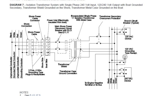
Very well-said. However, unless I misunderstood, your statement is worthy of clarification, an iso xfmr does not necessarily negate the need for an ELCI, with one exception, shown below (and see the schematic from ABYC E-11).

ABYC E--11.11.1 An equipment leakage circuit interrupter (ELCI) or Type A residual current device (RCD) shall be installed with or in addition to the main shore power disconnect circuit breaker(s) or at the additional over-current protection as required by E-11.10.2.8.3, whichever is closer to the shore power connection.
EXCEPTION: Installations where an isolation transformer is installed within 10 ft (three meters) of the shore power inlet or the electrical attachment point of a permanently installed shore power cord and supported according to 11.14.4.1.3.


I agree, while installations where iso xfmrs are within 10 feet of the inlet do not require a main breaker, I too would not install one without that protection.

The idea behind the ELCI between the xfmr (located as close to the inlet as possible, every foot of wire between the inlet and breaker is unprotected, or only protected by a dock breaker, which is often questionable) and the shore inlet is to prevent a ground fault (between the boat's inlet and the ELCI) from leaking current into the water, wherein in it returns to its source, the shore-based dock transformer rather than the boat's transformer. After the transformer all current returns to the transformer, making it much safer.

Also, most shore power transformers can be wired as polarization or isolation, there is otherwise no difference, it's up to the installer, you can't make a determination as to how a transformer is wired simply by looking at it from the outside, you can often tell by looking at the terminal blocks, and certainly by testing with a multimeter. The distinction is subtle but important, a polarization transformer offers all the benefits of an isolation transformer, ensures correct polarity, enhances electrocution prevention, may offer boosting capability, however, a transformer wired in polarization mode offers no isolation or protection from dock, other vessel or shore induced corrosion. If you wire for polarization, you also need a galvanic isolator.

If you install a non-boosting transformer, and you plug into 208, you will get 104/208 on the secondary, which is not ideal, especially for 120 VAC refrigeration compressors. Without a transformer you'll get 208/120, which is generally OK since most (modern) 240 gear like HVAC compressors will run on 208 with no problem. It's one of the few instances where a transformer can actually be detrimental, and it is for that reason that I do not recommend installing non-boosting transformers.

This article goes into some detail on this subject (I'm currently working on an updated version; if anyone has any thoughts about content, or anything that it may not include, please let me know), including why one might choose to wire for polarization rather than isolation, both can be compliant with ABYC Standards. http://stevedmarineconsulting.com/wp-content/uploads/2014/03/Transformers.pdf
 

Attachments

  • Screenshot 2019-05-31 15.jpg
    Screenshot 2019-05-31 15.jpg
    124.5 KB · Views: 83
Inverters are on most boats now. I have two isolation transformers, one each for separate 30A shorepower inlets (run to a separate air conditioner and both cannot be connected together at the same time anywhere on the boat so no mixing and matching of the two sources). I also have a 3Kw inverter/charger. The isolation transformers will isolate stray AC current from the shorepower/marina side to the water around the boat.


Question: can the inverter become a source of dangerous stray current, as well, independent of the shorepower? And if so how do you prevent that other than an ELCI breaker downstream of the inverter assuming that this would provide that protection.
 
Any lethal voltage COULD cause a stray current, but the inverter doesn’t seem likely. On floating boat, if either the L or the N output conductor from an inverter from a dc ships battery supplied source, were to fall into the water, a dangerous condition would result. An earth leakage breaker at the inverter output should trip on this fault.
Not a particularly common fault, i would guess.
 
Question: can the inverter become a source of dangerous stray current, as well, independent of the shorepower? And if so how do you prevent that other than an ELCI breaker downstream of the inverter assuming that this would provide that protection.

When you say "stray current" I assume you mean in the dangerous form, which can cause death or injury and not stray current corrosion? If you are referring to electrocution risk, electricity returns to its source; inverters, along with generators and shore power transformers, when the source of power, exhibit this phenomenon. In these cases leakage will not travel through the water because it has no reason to, it's not a path back to the source. This is why an isolation/polarization transformer makes for a safer shore power installation.

Shore power, on the other hand, for all intents and purposes, originates at the transformer in the marina parking lot or head of the dock, and thus leakage will travel through the water to return to that source.

I have yet to encounter a verified case of electric shock drowning (ESD) or in water electrocution from an inverter or genset, if anyone knows of a verified case please share.

Having said all that, inverter/genset and vessel wiring faults can still occur aboard, which can lead to electrocution, just not in water electrocution or ESD, and fire, so an ELCI on the inverter (and genset) output, along with GFCI receptacles, is still a good idea.
 
Back
Top Bottom