Towards a Balanced House Charging Design

The friendliest place on the web for anyone who enjoys boating.
If you have answers, please help by responding to the unanswered posts.

JDCAVE

Guru
Joined
Apr 3, 2011
Messages
3,010
Location
Canada
Vessel Name
Phoenix Hunter
Vessel Make
Kadey Krogen 42 (1985)
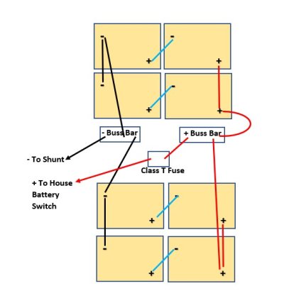
As mentioned in an earlier thread, I have replaced my 10 X T-105's Golf Cart bank with 8 X T-105's. The previous bank was not "as balanced" in its charging design as preferred, so I have designed a new arrangement as shown in the schematic. In addition, I would like to move the overcurrent protection (Class-T) closer to the battery terminal.

Some points:

1) the cables from the battery boxes to the buss bars will be of equal length.

2) the positive cabling from the battery boxes to the buss bars will be in loom.

3) total length of cable from the battery box to the Class T fuse will be 3'.

4) all cabling after the fuse and buss bars will be as before.

5) as before, this is a 12 VDC bank.

This is proposed at this time. No work has been done. The Class T Fuse is currently after the battery switch (some considerable distance from the battery boxes) and it is "probably" not "approved" under ABYC guidelines.

I should say that I got 9 seasons out of my last bank of T-105's. After 2 weeks at rest, the individual batteries were at 6.45 volts and within 0.02 of a volt of one another. I hope these last accordingly.

Any comments or suggestions most graciously accepted.

Jim
 

Attachments

  • House Bank Charging Design.jpg
    House Bank Charging Design.jpg
    39.6 KB · Views: 63
Last edited:
Have you looked at the Victron lynx distributor? It would replace the buss bars and fuse holder.
 
Jim, I will follow with interest. Your drawing shows me two battery banks joined together as +/- to feed is separated. Is it good as the if all 8 were joined with one +/- ends I am looking to learn.
 
It's easy to say, so here goes....


The best place for the battery fusing is in the wire from the battery to the buss bar, perhaps located right at the buss bar. Something like the Victron distributor might make this easier. I have also seen fuse holders (like all of mine) where one terminal is bolted right to the buss bar. That keeps the fuse closest to the battery, as encouraged by all the standards.
 
I'll admit I am not all that familiar w the Victron unit but wonder if it really simplifies or is cost effective?
Quick glance the Victron Lynx Distributor looks more like a "distribution" tool than a tool for "combining" inputs. I guess it could work in reverse but how is it beneficial or cost effective? $200+ and (4) fuse$ to replace a buss bar and (1) fuse/ fuse holder?

Jim
If you really want remote monitoring maybe the above unit has benefit but if not it seems like an unnecessary and expensive option.

Why not eliminate the Pos buss and simply connect the 2 cable lugs to one post of the Cl T fuse?
Couldn't the same be done on the Neg side using one shunt post?
I can see using buss bars if the 4 batty banks were wired independently but with only 2 banks it may be simpler to eliminate them and have fewer terminal crimps & connections ( which in itself seems like a benefit).
For large batty banks the Cl T is the preferred choice and not sure the Victron unit allows that. If each pair of battys connected individually to the Victron unit it MAY get around the Cl T reqmt but I'd be more comfortable with the Cl T as ABYC specifies.

I dont know if physical space requires the separation into 2 banks of 4 battys but if not SteveKs point may also be worth considering. You can connect 4 batty pairs into one balanced bank and have one Pos & one Neg cable.

I think the suggestion above of connecting the Cl T fuse directly to the buss bar has been challenged in another TF thread as not being in ABYC compliance when fuses used w/o the corresponding fuse holder. You get to decide whether ABYC compliance is important to you.

I think your sheathed 3 ft cables satisfy the reqmts. See
https://marinehowto.com/battery-banks-over-current-protection/

I'm no sparky expert so take my comments as food for thought & consideration. If attractive you might see if any others can poke holes in the above.
 
Last edited:
I'll admit I am not all that familiar w the Victron unit but wonder if it really simplifies or is cost effective?
Quick glance the Victron Lynx Distributor looks more like a "distribution" tool than a tool for "combining" inputs. I guess it could work in reverse but how is it beneficial or cost effective? $200+ and (4) fuse$ to replace a buss bar and (1) fuse/ fuse holder?

The lynx distrubutor is basically a bus bar for 4 negative and 4 positive connections and a fuse holder for each branch. There are led lights for each branch that monitors the fuse. If you add up the cost of bus bars and fuse holders, it's not that much of a difference. It saves space and makes it easy to see the condition of the fuse. It makes more sense if you use the spares for things like emergency bilge pumps etc.
 
Thanks for the input. I’ve read through CMS’s comments on overcurrent protection of battery banks and cabling. The Victron distributor is an option however, I don’t need the monitoring capabilities and the fusing is not Class T, which would be preferred if there was a short circuit in the battery cables. The short Circuit current raining for this bank would be 13,000 amps at 12 volts and only Class T are certified for this amperage. CMS is pretty emphatic on this point. There are physical limitations that prevent getting much closer than 2-3’, which is why I’m using loom to protect against shorting.

I could use a Terminal Fuse block but would need one for each battery box.

Still thinking about this.

Jim
 
Last edited:
…Why not eliminate the Pos buss and simply connect the 2 cable lugs to one post of the Cl T fuse?…


Good point! I’m going to think about that. Note, I already had the Class T fuse block so only have to move it.

The batteries need to be contained because of acid spillage. So they need to be in boxes, unlike AGM setups. The batteries are in place in their boxes. They are currently cabled as previously: (+) and (-) cables on either side of the bank.

Jim
 
I’m not one to question someone’s motives, but I’m wondering what the expected gain would be?
You got nine seasons out of the t-105s and put back the same batteries. They were all very close in volt readings at rest, so it would seem they were all working just as hard as their neighboring batteries. Also interesting is the resting voltage. I just replaced a couple of banks of t-105s (16 batteries total) they were closer to 6.30-6.35 at rest. Not sure what they’re age was, but boat records indicate at least 12 years. T105s are pretty bulletproof.
 
One small suggestion. Could you replace the negative buss bar with the shunt? It would be no problem putting 2 cables on one post of a shunt. Would simplify if its possible.

Ken
 
I’m not one to question someone’s motives, but I’m wondering what the expected gain would be?
You got nine seasons out of the t-105s and put back the same batteries. They were all very close in volt readings at rest.

My thoughts exactly. There are many ways to reconfigure your T105s JD, but given your previous success it would seem you’ve already got a decent setup even when dropping to 8.

My T105s and most others benefit from a few basics:
- A good charger
- Good location for easy water checks
- A BMK or similar for health checks
- Don’t abuse them

I’ll leave house bank fuse locations to smarter minds than mine, remembering of course ABYC vs reality arguments for a few decades now.
 
By your numbers I suspect there are no balance issues with the current wiring. Personally I don’t like the idea of having a single fuse failure taking out my whole house bank. It would be pretty simple to add another switch and fuse creating two independent isolatable banks. Each fuse would need to be half of what you currently have.
 
OP mentions a shunt but didn't elaborate on the monitoring system.
Some monitors (I have a Balmar SmartGauge) require connection to a common battery terminal and don't like being connected through a switch for V monitoring.. That is worth considering in the whole scheme of things.
 
Thanks for the input. I’ve read through CMS’s comments on overcurrent protection of battery banks and cabling. The Victron distributor is an option however, I don’t need the monitoring capabilities and the fusing is not Class T, which would be preferred if there was a short circuit in the battery cables. The short Circuit current raining for this bank would be 13,000 amps at 12 volts and only Class T are certified for this amperage. CMS is pretty emphatic on this point. There are physical limitations that prevent getting much closer than 2-3’, which is why I’m using loom to protect against shorting.

I could use a Terminal Fuse block but would need one for each battery box.

Still thinking about this.

Jim

Great catch on the class T fuse.
 
The Magnum BMK kit and ME-RC is connected to the Shunt, so the bank is monitored.

The only additional piece I would need is a single buss bar to connect the negative cables. The class T fuse holder would be repurposed and moved a lot closer to the bank, where it would be more appropriately situated. The positive cable from the two,boxes would connect to the battery end of the fuse holder. A few extra lugs also required. I have leftover cable sufficient for this. The revision would actually would result in shorter cabling overall, which is a further benefit l think.

I think this would be an improvement of the existing configuration, at little cost.

Jim
 
Jim
Can the shunt serve to also replace the Neg buss by connecting 2 cables to the batty end?
 
Jim
Can the shunt serve to also replace the Neg buss by connecting 2 cables to the batty end?


No. It’s located too far from the battery boxes for that purpose.

Jim
 
No. It’s located too far from the battery boxes for that purpose.

Jim
previously you said single buss bar to connect all negative. You mean the two from the batteries, correct, not any from the rest of the boat until after the shunt.
 
previously you said single buss bar to connect all negative. You mean the two from the batteries, correct, not any from the rest of the boat until after the shunt.


Yes. From the boxes to a buss bar and then to the shunt. In other words, I will shorten the existing negative cabling that goes from the house bank setup that is currently in place and connect it to the buss bar and with a cable from each box to that bus bar.
 
Just think about the "system" and total run distances.
Running to a buss bar and then to the shunt you need to add both for total run length.
If shorter runs to buss bar but then a longer common runbto the shunt are you really gaining anything? Vs longer run from batty to shunt?
Is the buss bar to shunt cable larger (2X area) to break even vs separate cables?
And that ignores the intermediate terminals & connectons vs straight cable runs.
The differences may not be huge but I would favor fewer connections if cable size/losses are equivalent.
 
As mentioned in an earlier thread, I have replaced my 10 X T-105's Golf Cart bank with 8 X T-105's. The previous bank was not "as balanced" in its charging design as preferred, so I have designed a new arrangement as shown in the schematic. In addition, I would like to move the overcurrent protection (Class-T) closer to the battery terminal.

Some points:

1) the cables from the battery boxes to the buss bars will be of equal length.

2) the positive cabling from the battery boxes to the buss bars will be in loom.

3) total length of cable from the battery box to the Class T fuse will be 3'.

4) all cabling after the fuse and buss bars will be as before.

5) as before, this is a 12 VDC bank.

This is proposed at this time. No work has been done. The Class T Fuse is currently after the battery switch (some considerable distance from the battery boxes) and it is "probably" not "approved" under ABYC guidelines.

I should say that I got 9 seasons out of my last bank of T-105's. After 2 weeks at rest, the individual batteries were at 6.45 volts and within 0.02 of a volt of one another. I hope these last accordingly.

Any comments or suggestions most graciously accepted.

Jim
Exactly the configuration we have. It works.
 
If you use the buss bars then connect each lead from the + and the - battery group cables either side of the load side lead so a balance is maintained from the two battery leads to the load side.

OR

if you stack the + and the - battery leads reverse stack one of the sets of leads.

ie. If you install on the + buss, battery cable # 1 first and battery cable # 2 on top , then the hold down washer and nut
then reverse the order on the - buss.
The different flip order will help balance the charging/discharging.

Minute yes but not to the batteries.

JMO
 
I have a similar house bank on Lily D but only 6 T105's. I also had a single fuse at some distance from the battery boxes, one of which is well separated from the other 2 boxes.
I added a Blue Sea terminal fuse on the positive terminal of each set of two batteries which I believe is within the interrupt rating of the terminal fuse and should satisfy the distance requirement. No rewiring was required.
 
So I went ahead with the design:

Box 1 (original interconnecting cables)

IMG_5890.jpg

Box 2 (original interconnecting cables)

IMG_5891.jpg

Class T fuse and negative bus bar

IMG_5883.jpg

Class T with cover

IMG_5884.jpg

Although fully charged batteries were left to charge for a few days.

I then did a load test with a 1000 watt inverter load and checked the contribution from each box with a clamp meter. The total current draw was about 100 amps and the boxes were about 8 amps different: one at 54 amps and one at 46. So, lots of head scratching. I swapped the cables (connecting to T fuse and - bus bar) from one box to another and there was no difference. I concluded that something was wrong with short cables that interconnect to the batteries. I suspected poor crimps and or use of different lug sizes to studs: some were 5/16 and others were larger. Also some of the lugs were bare copper (no remaining tin).

So I replaced all the interconnecting cables, with matching sizes and lugs, these pre heat-shrink:

IMG_5990.jpg

I repeated the load test which indicated current draws from each box within an amp of each other.

I would never have known these issues with these interconnecting cables if the boxes had been directly cabled together. So the take home message is to check those cables as unbalanced draws could ultimately affect which batteries fail down the road.

Jim
 
Last edited:
Jim, good report. I would be interested if you explored why those shorter cables were the issue, perhaps a resistance test. If you discovered an obvious reason it would offer us a way to look for it.
 
Jim, good report. I would be interested if you explored why those shorter cables were the issue, perhaps a resistance test. If you discovered an obvious reason it would offer us a way to look for it.


Nothing that diagnostic or elegant, I’m afraid. The initial test was to rule out the supply cables in and out of the box. When these were found to be good, it was then either the connecting cables or one of the batteries was not performing to spec.

Jim
 
Last edited:
I spoke too soon about this. Self congratulatory back-patting was premature. There are differences in the "amps out" on a 1000 watt inverter load. About 10 amps different: 60 amps and 50 amps from the two boxes. The test was done on fully charged batteries.

As mentioned, all new cables, all new lugs. Cables are identically sized. No corrosion. I'm at a loss and now believe there may be variation in the batteries. The batteries are new T-105's. I've tried changing the connections, "which cable is on top and which one is on bottom" No difference.

Any thoughts? (see the above photos for the outline of how these are cabled.

Jim
 
Jim,
The original box 1&2 cables were changed. Assumption is they are now as pictured originally.

There are differences in the "amps out" on a 1000 watt inverter load. About 10 amps different: 60 amps and 50 amps from the two boxes.
10 amp difference draw by the inverter from different box?

You could try
- first swap the pos leads from battery to busbar
no change
-swap neg leads from battery to busbar
No difference on output
disconnect all wires from all batteries and let rest overnight. Then do volt test on each 6V. An electrolyte test each cell

New batteries, good time to find out if there is a weak cell.
I suspect one of the main cables to busbar, same as reason you changed short cables.
 
Jim,

The original box 1&2 cables were changed. Assumption is they are now as pictured originally.


10 amp difference draw by the inverter from different box?


You could try

- first swap the pos leads from battery to busbar

no change

-swap neg leads from battery to busbar

No difference on output

disconnect all wires from all batteries and let rest overnight. Then do volt test on each 6V. An electrolyte test each cell


New batteries, good time to find out if there is a weak cell.

I suspect one of the main cables to busbar, same as reason you changed short cables.


I swapped the main cables to the two boxes and got the same result. I haven’t swapped the inter battery cables but I could try that. I made new inter battery cables and am confident on the crimps. I used the FTZ crimp tool. They sure look good to me.

Which is why I’m wondering about the batteries. I did a voltage test earlier with the batteries and they were all within 2/100’s of a volt of one another, 6.45-6.47 volts if I recall.

I don’t have the ability to test the electrolyte. Have to think about that.

I had topped up the batteries with distilled water a couple of months ago and put in very little. It is possible that there may be slightly different electrolyte levels in the cells.

Jim
 
Back
Top Bottom