O C Diver
Guru
- Joined
- Dec 16, 2010
- Messages
- 13,187
- Location
- Fort Myers, Florida
- Vessel Name
- End Of The Line
- Vessel Make
- Trinka 10 Dinghy
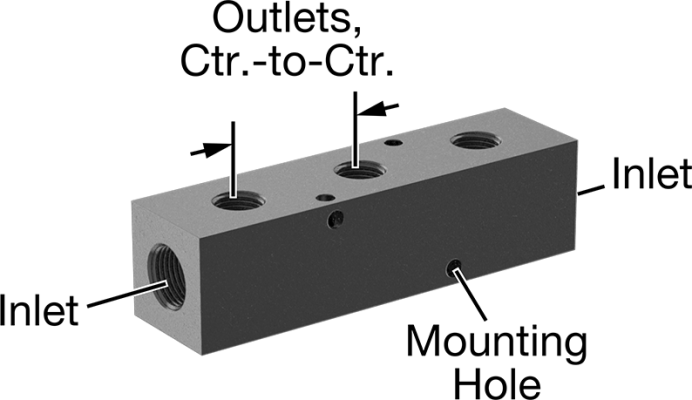
There is a section of the tank top where thicker aluminum is welded to the top, maybe 4" by 16". At one end of the tank there are four return fittings (two of which are used). At the other end there are four fittings with two for supply lines (with draw tubes). At each end of the tank there is one vent line in one of the fittings. The two supply fittings have tubes (draw tubes) welded to the pipe bushing that reach to within an inch or two of the bottom of the tank.is the female pipe thread welded to a hole on the top of the tank?
if the same hole is used as a source rather than a return, what tank fitting do you install there?
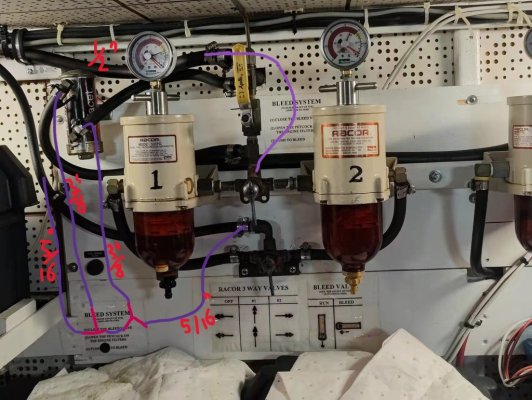
Each tank has a 1/2" drain valve at the lowest corner on the inboard side of the tank. This is where I connected my fuel polisher / transfer system.
Ted