10kw Kohler Generator 10R0P23 Schematics

The friendliest place on the web for anyone who enjoys boating.
If you have answers, please help by responding to the unanswered posts.

grehard1

Member
Joined
Sep 6, 2023
Messages
18
Vessel Name
Islandtime VI
Vessel Make
DeFever
I have a 1976 DeFever trawler with an original Kohler 10kw Generator. Here are the specs:
Model: 10ROP23
Controller: D-268923
Motor: Perkins 4.107
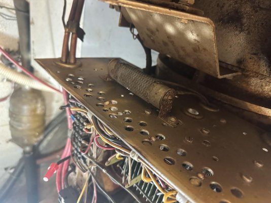
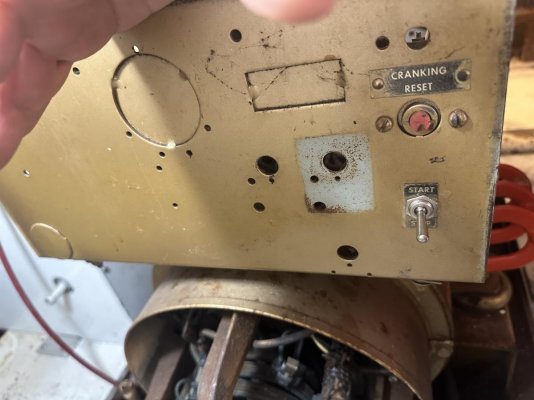
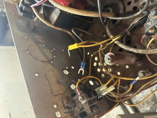
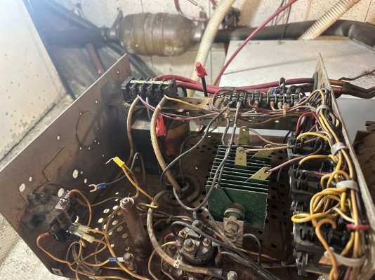
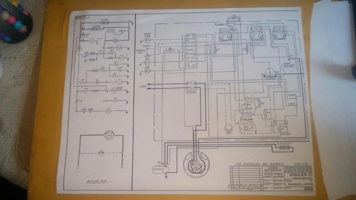
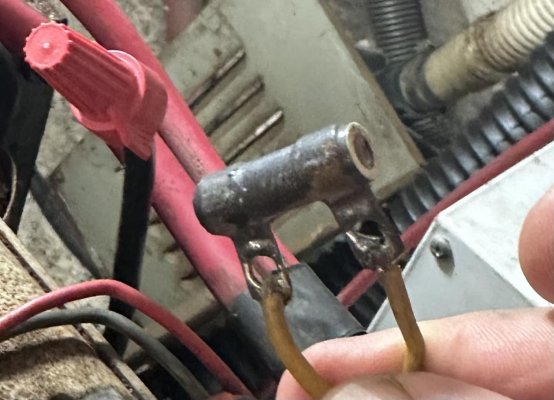
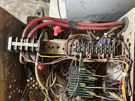
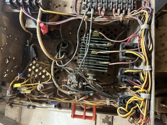
The engine starts and runs. Oil pressure and temp sensors work properly but do not have AC voltage. Generator sat for 7 years on the hard so I figured the field needed to be flashed. Check brushes connections, relays and flashed field. Still no voltage. Generator trips after running for 30 seconds when overcrank breaker pops due to no AC voltage. Upon inspection it appears there is something missing in the controller. There are two wires not attached to anything and an empty hole where it looked like a switch and plate were attached. Can't find a wiring diagram to figure out what is missing or where to connect the leads. The yellow wire runs back to the 1CR relay and the black wire runs to what I think is either a resistor or diode on the outside of the controller. The lead off the diode/resistor runs back into the controller and is attached to the ground post by the over crank trip. I have attached pictures of the two leads, controller. The two capped wires were off the A3 lead of the transformer. One was attached to the A1 terminal and the other was attached to the L1 terminal along with the output of the A1 lead. There is no A3 lead off the generator. Appreciate any assistance.
 

Attachments

  • IMG_4129.jpg
    IMG_4129.jpg
    116 KB · Views: 31
  • IMG_4128.jpg
    IMG_4128.jpg
    100.3 KB · Views: 24
  • IMG_4127.jpg
    IMG_4127.jpg
    116.7 KB · Views: 26
  • IMG_4126.jpg
    IMG_4126.jpg
    177 KB · Views: 31
In my way of thinking, the fact that it starts, stops cranking, and runs for 30 seconds before shutting down tells me a lot. And, the fact that I see a big, ole' selenium rectifier in the middle of the board also tells me a lot.

During the 30 seconds that it runs, check oil pressure with a mechanical gauge and make sure it comes up. Then, open the water temp and oil pressure wires and just make sure that isn't it.

If that ain't it, the next place to check is 1CR. Does it look okay? If so, it probably is. The next thing to check is that big selenium bridging rectifier in the middle of the board:

-- https://en.wikipedia.org/wiki/Selenium_rectifier

Those things have about a 15 minute lifespan. Okay. I'm exaggerating. But, their lifespan is way shorter than anything else on that board. Check it.

If it is bad, you can probably replace it with a modern silicon bridging rectifier. I guess that might provide a little less over-current protection, but in the main should be fine. You'd just want to size it right, I think. Go big.
Also, if the rectifier is bad, it isn't super likely to cause other problems because it often fails open or high forward resistance. But, if it drops resistance, it could easily eat other things. In any case, keep a look out along the potentially impacted paths.

The next place to check is down on the generator, there is a sliding bar resistor known as R1. It calibrates the field. Check it with an ohm meter (with the generator off, etc). If it is open, no 1CR. If it is open from the generator to the slider, loosen the slider, move it a little bit, and tighten it back down. Hopefully it has gotten to a better part of the coil and is now fine. If not, check it end to end to make sure it isn't open. If that isn't it, check the wire to the slider. If that isn't it, you'll need to replace it.

If R1 isn't it, there is often a 100-ohm resistor, R3, near the CC relay. Check that. If it opens, once 1CR has switched, CC will drop out and ITS will trigger.

I'm using some nomenclature here, R1, R3, CC, CR, 1CR, 1TS that is commonly used on this vintage of Kohler generator. But, not necessarily.

If you don't know which resistors are which on the board -- you can check them all. Desolder one side, as needed.

What does it look like is missing to me? From what I can see, chunks of the battery charging circuit. I wouldn't use it anyway. Use a modern charger powered by the 120v. But, I really can't see with the photos at angles vs straight down.

Can you post a picture looking straight down at that controller?

Just to double check, the schematic isn't taped to the inside of the top of the controller, is it?

On the tag where you got the drawing number and the model number, is there a spec number?

I've included a schematic that may be sort of similar to (but not the same as) yours (it is 3 wire, 120/240v), just for reference. I've also included the schematic for a simpler controller of the same era, just in case things are clearer there, as an example for learning.

Also....you are playing with sparky here. There is AC voltage where you will be poking. And, there are metal grounds all around. DON'T EVEN THINK OF TOUCHING IT UNLESS YOU ARE 100% COMFORTABLE DOING IT AND WITH THE RISK. Same goes for any repair you make or attempt.

I'm just thinking aloud. I'm not suggesting that you touch any of this. What you decide to do is up to you!

Happy hunting!
 

Attachments

  • ControllerSchematicOriginalPhoto.jpg
    ControllerSchematicOriginalPhoto.jpg
    86.7 KB · Views: 44
  • 20190206075013386.pdf
    181.2 KB · Views: 51
Last edited:
I am perplexed with all the resistors in the control circuits. Seems odd.
 
Appreciate the Assistance

Thanks for all the great info. Unfortunately, there wasn't a wiring diagram on the inside of the controller housing. All I was able to find was the model, controller and serial number. I have attached two pictures of the controller from the top down. The nomenclature plate also says that it is a single phase 120V 60Hz generator as well. I have attached 2 pictures of the controller from the top down. The A1 and A3 leads off the big transformer were both put in the A1/L1 terminals. I capped off the A3 leads. On the two unconnected leads, the yellow one has 12V even with the generator not running.
- Checked all the replays. They don't look burnt, the contacts are good and they are all wired per the schematic.
- Found the test procedure for the selenium rectifier. It tested good. No sticky residue or sweet smell.
- Cleaned the band around R1 and tested it. It was good.
- Checked all the other resistors. The resistor R7 from 1CR to "C" tested open. I'll need to replace that. The diode checked out ok. I took a pictures of the resistor before I took it out.
- All other resistors check out ok and everything is wired as per the diagram. I'll change out the resistor and see where that takes me. Thanks for all your help and the diagram. R/Greg Rehard
 

Attachments

  • IMG_4165.jpg
    IMG_4165.jpg
    106.3 KB · Views: 24
  • IMG_4160.jpg
    IMG_4160.jpg
    177.8 KB · Views: 28
  • IMG_4158.jpg
    IMG_4158.jpg
    195.2 KB · Views: 26
When you say that everything is wired per the diagram, which diagram? Thanks! Same as the 120/240 unit one I sent over?
 
Yes. The diagram you provided. All of the elements were the same. Also, I got a 30 ohm resister for R7 and will replace it this afternoon.
 
Okay. I'm still at work and haven't had a chance to take a look. Just make sure the 30-ohm resistor is rated for the wattaged.
 
Okay. I just took a look at that schematic again. R7 being open, by itself, could easily cause the problem. It is bringing the 12v to the field and armature.

But, is the rectifying diode, shown as RE2, just downstream of it good?

It is possible that the resistor just slowly opened with heat and time. It happens.

But, that diode also looks like it separates this part of the circuit from the supply side of the charging circuit. Since parts of the charging circuit seemed to be missing, it is possible that something at that end was shorted and took out both the diode and the resistor.

Obviously, there could be multiple problems. But, I think if you get those two components squared away, there is a really good chance you'll be up and running.
 
Last edited:
Thanks for the input. I tested the diode with the multimeter and it passed.
 
I am perplexed with all the resistors in the control circuits. Seems odd.

R1 is a slider down on the generator, itself. It is used to adjust tune the field and, thereby the baseline voltage output of the generator.

R2 and 1R2 are pretty gross. They are current limiting for the charging circuits and basically burn off as heat what the battery isn't taking. High (1R2) and low (R2) charge modes have different resistances to achieve different current flows. No smarts here.

R3 is current limiting for the supply to the CC relay. The generator uses SPST start, not a momentary start. This relay cuts off the starter once the generator is running. Current through R3 drives this relay, turning off the starter. (I miss identified R7 as this resistor in an earlier post. In the OP's case we actually knew R3 was good because the start and run behavior was fine, except for safety timeout).

R4 is current limiting for the 1TS thermal switch so that, during the 30 seconds it is switched on during a failure and before it pops the breaker, the current doesn't burn out its internal heater.

R5 is non-existent. I don't think there is one in this controller version.

R6 is current-limiting for the start-stop solenoid, but is bypassed during starting via the "R" terminal on the starter to ensure that the solenoid stays engaged even when the voltage drops during starting

R7 is actually the resistor I meant to tell him to check. I apparently misspoke when I identified it as R3 (Glad he found it, anyway!). It is current limiting for the field supply. It being open means no field. (Current can't flow backward through it once running, bypassing the charging circuit and always charging, because of the 1RE diode).

At least this is my hot take.

Cheers!
-Greg
 
Last edited:
Nothing like brute force automation. These days companies would throw in a $2 uP to do the thinking. Arguably less reliable.
 
Nothing like brute force automation. These days companies would throw in a $2 uP to do the thinking. Arguably less reliable.

The first time I opened one of these I stood over it, staring down with a mixture of awe and confusion, like I was looking through a portal to a different universe. I counted barely a few dozen components, yet I had no idea where to start!

Eventually some folks on SmokStak gave me some hints and I was able to sort that one out. Now all of the old Kohlers all sort of look alike! It seems like they had a very consistent design and implementation philosophy for a long, long while.

I still can't get past the huge ~1" wide, ~7" long resistors some of them have hanging, exposed, off the back for high charge.
 
Still troubleshooting

Replaced Resistor R7. Went big with 25 watts. When I started the generator it went up to 7 volt a/c then settled down to 2.5V. Let it run for about 15 seconds. No change. Just on the off chance I tested the diode wrong, I jumped it, same thing. I'll make sure 1CR is getting 12V from "C" (Solenoid) I guess R1 could be bad. Thanks.
 
Are you starting it under no load, with the output breaker closed?

The fact that it went up to 7v before settling at 2.5v is interesting to me. If it had just been 2.5v, I'd have suspected that it was just from the residual magnetism. But, the fact that it went up to 7v leads me to believe that some voltage is building before being regulated down. It also leads me to believe that the problem isn't a loss of residual magnetism or that the generator windings are shorted.

This really seems like a field problem to me. I'd check and recheck R1. I'd make sure that, not only is the resistor good, but the connections to it are good. Then, mark the position and move it 1/8" in each direction. Does anything change? If so, how? If not, what about 1/4"? I'd look not only at the generator output, but also at the field output, itself.

I'd also check the brushes to make sure they are making good contact and have good connections and undamaged wiring. I;d also check the slip rings. And, I'd check the generator windings for a short.

Beyond that, how did you check that selenium diode? I'd want to /really/ check that.

What that part of the circuit does is to basically act as a voltage regulator preventing the voltage from drooping under load. That transformer is what is called a conversion transformer. It is basically an autotransformer that bleeds off a little bit of the AC current, proportional to the load. This current gets rectified to DC by that selenium bridge rectifier and the resulting DC is fed into that AUX field winding.

That surge protector is there to protect the coil, and especially the rectifier, from a momentary overload, especially as the load on the generator changes rapidly, e.g. HVAC pegs it. I don't know what the original surge suppressors were, maybe GDTs or selenium devices. I guess replacements would probably be MOVs, especially if the rectifier were replaced with a big, high-current rated modern silicon device. If I had to replace either the rectifier or the surge suppressor, I'd replace both with modern devices.

In any case, the idea is that, as the load goes up, the voltage output of the generator would normally want to sag. So, to adjust for this, they bleed off a bit of current from the load side via that transformer, such that the current that is bled off is proportional to the load. This current then powers the aux field, which boosts the primary field as the load goes up, thereby preventing a voltage sag.

In other words, as the load goes up, some current is bled off of the conversion transformer, gets rectified by that selenium rectifier, and the increase in current boosts the auxiliary field, preventing the generator output from drooping under load.

In my model of the universe, which isn't necessarily correct, most of the work is done by the primary field which is statically regulated by R1. What goes on with the transformer, rectifier, and surge protector is just a supplement to fill in for the droop voltage in response to changes in load. So, in my mind, a problem with this part of the circuit should have a modest impact, not put the output down to the low single digits.

I'm somewhat confident that, if that rectifier fails open under load, it'll basically do the same thing to that transformer as you'd do to your alternator by moving a break-before-make switch when it is running. The voltage would jump instantly, the current would instantly jump, and it would instantly burn out. The rectifier and surge protector would need to be replaced with new silicon versions and the transformer would need to be rewound by an electrical shop.

But, I'm concerned that, if the rectifier fails short, due to some subtlety, the circuit might behave very differently than I suggested above. Basically, my brain has a nagging minority report. I can also imagine a world in which that rectifier shorts out, so it fails to rectify the AC into DC, so we now have AC going into the aux field coil. And, that makes for a rapidly changing field that is pretty coo coo for cocoa puffs. I can imagine that this whacky AUX field fights the primary field enough to prevent the primary field from building up.

I guess, if it were me, I'd repeat my spot checks of everything R1, then spot check the brushes and other moving parts, then spot check the generator windings, then spot check the rectifier, transformer, and surge suppressor. I might try using a large static magnet to stand-in for the residual magnetism, in case that was a problem and/or do a field flash.

And then, from there, I'd feel pretty unlucky and stop poking at it. I'd work systematically and trace the field voltage and the trace the generator voltage every step of the way until I found the problem. I'd check each component statically, and then as it operates in the circuit. Eventually the problem would show itself.

Keep in mind that I'm just some random guy on the Internet. I assure you that I am not a generator repair person. I'm just another boater who likes to poke at things and has poked at a lot of things.

I write about this only as an intellectual exercise. I don't recommend that you or anyone else actually play with sparky. In fact, I recommend that anyone who isn't super knowledgeable and confident don't do it. A "dead" generator can suddenly start making high voltage at any time. If there is a regulation problem it can make way more than it is supposed to. Shorts involving batteries can spark, generate heat, or even start fires. Field flashing a generator can send high AC voltage back one's way. Improper testing procedures can damage components. Improper repair, including improper component selection or technique can cause immediate problems or leave a ticking time bomb. Repairing one aspect of a generator without fully inspecting the system and finding and rectifying other problems can also result in immediate and time-bomb risks. No output voltage, low output voltage, or high output voltage can cause devices to fail to function, become damaged, or become hazards; this includes life-safety devices such as CPAP machines and oxygen concentrators as well as potentially very high risk devices, such as lithium battery chargers, etc. There are a bazillion other ways that serving a generator can cause injury, death, and/or the loss of property to those involve as well as third parties. The risks are real. Be warned.
 
Last edited:
In thinking about this a little more, if this were my generator, and I turned up really stumped, I'd be tempted to remove the entirety of the regulator circuit (except the aux field coil, itself, which would be hard to do): the surge suppressor, the transformer, and the rectifier.

In my mental model, this would leave the generator without the ability to regulate for load, and likely with a low voltage output -- but not a super low voltage output like you are seeing. This would either show the regulator circuit to be part of the problem or would show that it isn't part of the problem and let me focus with confidence on the rest.

Of course, when it comes to re-engineering things like this, I always benefit. Sometimes it is the step I expect it to be toward solving the problem. And, sometimes I learn something totally unexpected. It is the cost of the lesson that can be highly variable, and sometimes quite high!

Again, I'm only thinking aloud about what I might do. I'm not making any suggestion at all as to whether or not such is a bright idea or as to what you should do or consider.

See warning in my earlier post!

Good luck!
 
Last edited:
Smokstak has some writings of the selenium poison smoke. Worth a read if working around them. Especially in a closed space.
 
I chatted for a few minutes with a friend of mine who is pretty good with this type of thing.

He pointed out that, although AC going through the aux field could potentially have a cancelling effect upon the main field, that won't likely be the case here. Because the aux field is proportional to the current going through the load, and there is no load right now, there is no meaningful aux field. Near 0, even unrectified remains near 0.

So, I'm going to go back to this being a problem with either the field or the brushes. So, if it was me, I'd recheck everything starting from R1 on up to verify field current. And then to check everything starting at the brushes on up, verifying the armature. I'd clean and/or dress the brushes, if needed. I'd move R1, if needed, and replace it, if needed. And, I'd also check the generator windings just to make sure they aren't shorted, bt they don't look shorted.

I think the problem space is looking much smaller when one looks at what is working, what isn't working, and what's involved right now.

My thoughts, at least.
 
Thanks for all the good advice. I'm being super careful. All the troubleshooting is being done cold iron.
- I'm testing the generator with no load generator breaker open.
- I'll relook at R1. The brushes have very little wear on the and make good contact with the rotor. The rings on the rotor are smooth and shiny.
- I checked the selenium rectifier by checking the forward and reverse bias with the multimeter set to diode mode. The I found a YouTube video that tests the rectifier by putting the meter on the positive terminal and checking the flow to the two other outputs. One way should be open, the other will have a reading, then do the same on the negative terminal. It passed that test. I also read that if the rectifier had a sticky residue or (of course) a sweet smell, it was bad.
 
Thanks for the info from Smokestack. I read the selenium rectifier posts. Yes, could be a problem but I'm working in a well ventilated area, hatches open fans going.
 
Maybe the next step could be to check both sides of R1 and the tap from it along the path to make sure you've got good field current while it is running. Then doing the same thing along the wires from the brushes. Then, I guess check the generator for a short, but this really doesn't seem like that.

Is it still getting up to 7.5v the settling back to 2.5v?

Usual disclaimer and warnings apply!
 
Last edited:
Got sidetracked with other boat jobs but have gotten back to the generator. The resistance of R1 is 3 ohms. Is that OK? Also checked the transformer/rectifier combination by disconnecting A1 from the generator and putting in a 120 VAC source. When I did that, I could hear 1CR trip and the power available light came on at the ship/shore panel. Transformer secondary output was 30VAC and 30V DC at the rectifier. The schematic showed a step up transformer so shouldn't the AC voltage to the rectifier be greater that 120V? When I disconnected the F1/F2 leads, I got barely got 1 VAC measured at L1/L2. Perplexing. Thanks for any insights. R/Greg
 
I've got a few spinning plates over the next few days and won't be able to sit down and look at the schematic until then. But, I will bounce back over to this post, probably over the weekend. This isn't one I can just jump on from my phone without that figure in hand. Standby! (Others might have some thoughts between now and then).
 
Here is the latest. I removed the A1 leads from the transformer and started the generator. It did the same thing. Voltage now peaks at around 20VAC then settled back to 2.5VAC. To re-verify the brushes and rotor, with the transformer out of the circuit, I backfed the generator with 110VAC for a second. It motorized the rotor so I know the lead, brushes and rotor are all good. Unless there is something I am missing, I can only think that there is something wrong with the stator windings. The wiring diagram says the 4 elements are wired in series so there could be a break in one of the wires or one of the stator pads is bad. At any rate, I guess the only way to be sure is to pull the electrical end and have a rewind facility take a look at it.
 
Back
Top Bottom