2006 Mainship 400 DC Wiring Diagram to share

The friendliest place on the web for anyone who enjoys boating.
If you have answers, please help by responding to the unanswered posts.

jefndeb

Guru
Joined
Jun 11, 2018
Messages
618
Location
US
Vessel Name
Indigo Star
Vessel Make
2006 Mainship 400
Hello,


I am installing an external Balmar Regulator for my new alternator and also a solar panel installation soon and to insure that I interface all this correctly I made a petty accurate diagram of how this boats DC system is configured.


None of the manuals or schematics I found ever matched what I had so I traced each wire to make sure for at least this boat, I had it right.


PS.Still not sure where to wire the MPPT charge output on this setup...
Thinking the "Common" of the House Battery Switch maybe?


Might not match yours but I thought I would share.


Vessel details-
2006 Mainship 400
Single Yanmar 6LY2AN-STP 440
Victron Multiplus Inverter/Charger (3K 120A Charge)
Victron 30A MPPT
1 LG NeON R 375 Watt PV
Balmar ARS-5H Regulator


Thanks,
Jeff
 

Attachments

  • Indigo Star DC.pdf
    184.5 KB · Views: 131
Wow, Jeff, I don't know if I would have the patience, time or flexibility to trace every wire like you did!

I appreciate you sharing it. I may find it somewhat useful for as I have two engines, it may not cover all the bases.

My current situation has two 8D's and the port battery starts the port engine and has some house load and the starboard battery likewise starts that engine and also has some house loads.

I am looking to add a 3rd 8D and combine with another 8D for a bigger house bank. I also want to get the windlass and thruster off the house bank since I installed the Balmar SG200 battery monitor last summer and the shunt can't take the amp draw from one of those devices and, I think, overheats thus making the monitor useless.

It also seems to create a resistance in the shunt after I run the windlass so I can't start the starboard engine without using the parallel start relay (and the parallel start switch at the flybridge doesn't work so I have to run down to the cabin).

Anyway, thanks for the diagram.
 
Jeff !
Very nice drawing you made. It will be useful for me. Thanks!
For you info I,ve done the same for the bilge pumps circuits.

I also have plans to improve the charging with a balmar.
But first I will try with a dc-dc charger from the startbatt. to the house batt. and perhaps trick the existing regulator into charge what’s required.
My house batt. is 720Ah deep cycle and my starting batt. is 105Ah AGM and it’s connected to two similars for thrusters bow and stern, together 315 Ah.

Mainship made a very poor installation. My thrusters got only 8,5V as lowest.
I have changed a lot and have now twice the force and very pleased how it works now.

I think it’s a good idea to connect your mppt to common!

As step no two if needed I will install the 160 A alternator without regulator I have, and put an external balmar regulator.
 
Jeff
Nice work and useful dwg.
You might consider submitting it to the TF Library as it would be easier for others to find (or point them to) than searching threads.
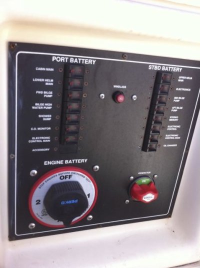
One question - you show a direct connection between your eng & gen start battys in addition to the ACR - If that is correct the ACR doesn't really serve any purpose - does it?

Also - if you are ever interested in adding an emergency start for your gen.
I'm guessing your switches are similar to mine (pic shown) another TFer tipped me off that the Gen on-off switch shown is replaceable with an exact fit 1-2-All - Off Sw and a short jumper to the adjacent House Sw gives an easy & quick way to "jump" the gen if needed. I changed mine as I have no charging on my gen batty and it also lets me "top it off" occasionally by combining w/ my house.
 

Attachments

  • Elec Batty Sw Panel.jpg
    Elec Batty Sw Panel.jpg
    46.5 KB · Views: 35
I have made a few updates to the diagram (as I realized stuff that was left out or wrong) and also showing where I think I will connect this new solar system input.

You say a direct connection, I guess it is yes, although through a battery switch..

I think that acr was installed by the po, in an effort to charge the generator start battery...via the alternator???

I noted last year that the Xantrex truecharge engine battery charger had an unused output, so I wired that to the generator start battery...not really knowing that the acr was also in the loop at that time..

Anyway, this diagram has helped me to better understand the system as a whole, its areas that could be improved as well...I am thinking of buying a victron Argo FET battery isolator as I have read that these older diode type isolators drop about .7 volts in the charge circuit. I have not verified that but I like blowing all my money on silly boat stuff....lol
 
Last edited:
Jeff
Eliminating diode isolators was one of the first projects I did on Bacchus. Details and links to alternate isolator technologies are on the Bacchus website... projects.... charging system mods.
 
Thanks for posting Jeff. Even though I have twins with no thruster it is still helpful ro me.

Don, with your added 3 way generator switch you could also, in theory, jump start the main engine from the generator battery correct? I’m pretty sure my group 27 would start my 4lhas in a pinch.
 
Doug
Agree it would work with my old / original MS configuration of combined house & start. I recently moved my start to my thruster bank to leave a pure house. The thruster bank is an AGM 8D now but plan to replace w 2 GP31 AGM when the time comes. The start wire run is about half the previous distance and ended up pretty simple. I added a power post near the starter to tie alternator output back to house using the old starter run so jumping from the house to start would be pretty easy. I'm thinking of a jumper easier than permanent and an additional switch... Im a KISS fan.
 

Latest posts

Back
Top Bottom