Adapting a hall effect sensor/magnet to existing alternator (W signal) tachometer

The friendliest place on the web for anyone who enjoys boating.
If you have answers, please help by responding to the unanswered posts.
Joined
Dec 24, 2019
Messages
998
Location
New Port Richey, Fl
Vessel Name
M/V Intrigue
Vessel Make
1985 Tung Hwa Senator
I just got done figuring out a solid way to drive your old original alternator driven W signal tachometers from a hall effect sensor/magnet mounted to the front of the motor and signal adapter for around $110. Alternator driven tach signals are not the best and can be finicky. But many times people want to retain the original tachometer but use a different signal that might be more accurate and less finicky. I went through several variations before I settled on this one and I hope it will be reliable and accurate. Really you can use these two items to drive any tachometer. Its just been that W signal tachs have been harder to adapt. I made a video outlining all the details on how too and what items. Hopefully its useful to someone. I know I looked and looked and there was no clear roadmap if you wanted to retain your W signal tachs but use a better signal.

 
I would like to upgrade my tach signal. None of my upper gauges work. But my tach at the helm doesn't pick anything up at startup until I give the engine more rpms maybe 1500-1800 then it works fine all through the rpm range from idle on up.

I'll have to take a look at your video. I've seen your other upgrades to the helm package and need to do some similar work. I definitely want all gauges at both helm stations to work reliably. Monitoring the single Ford Lehman 120.
 
I would like to upgrade my tach signal. None of my upper gauges work. But my tach at the helm doesn't pick anything up at startup until I give the engine more rpms maybe 1500-1800 then it works fine all through the rpm range from idle on up.


Charlie, its been my experience (on 2 different boats) that your issue with the tach not working until you rev the engine a bit is caused by a weak/worn alternator.


Ken
 
If you have an external regulator many times these have an output for the tach signal. My guess is these outputs are probably much more reliable than the typical signal from an internally regulated alternator.

I would imagine yours is an internally regulated alternator and I would also bet the alternator output coincides with the tach signal after reving. You might even just try cleaning all contacts and grounds on the alternator and alternator brackets.

My main reason for the modifications was simply to get a more reliable and accurate reading as well as wanting to use the tach of my choice in a full size gauge in either digital or analog or in my case one of each. There are several problems with alternator driven tach signals in regards to accuracy. Belt wear and slip is one. But also a change in alternator as well if pulley size is different. I just put on a Balmar and that Balmar pulley is much smaller in diameter than the stock Delco Remy 62 amp unit. Not sure if the stock tach would have had enough adjustment to compensate. But it doesnt matter now because the new system should be set and forget and much more accurate and reliable.

I will plan on cleaning all my contacts and checking connections and crimps then verifying alternator function.

I'm not really looking to upgrade per se. I'm at the repair, rebuild then replace stage. If I get to the replace stage, then I can evaluate the upgrade.

I would like to get all my basic gauges working as they should at both stations and add a couple different alarms. This work is probably a few months away, but I like to ask questions when the opportunity arises. That way it's in my mind for retrieval later.

Stay tuned for more questions from me in the future on this project of mine.
 
No problem at all. Obviously I just got done replacing gauges and rewiring both stations so if I can help in any way just let me know. I can say one of the best things I have done was eliminate harness plugs and gone to terminal strips.
 
No problem at all. Obviously I just got done replacing gauges and rewiring both stations so if I can help in any way just let me know. I can say one of the best things I have done was eliminate harness plugs and gone to terminal strips.

What are terminal strips? I also need to educate myself about proper use of buss bars.

Thanks
 
What are terminal strips? I also need to educate myself about proper use of buss bars.

Thanks

Well..on my helm station I had a plug with 9 wires going through it. Every time I had to change a gauge I had to cut the wire and splice it in or de-pin the plug and find an identical pin and re-crimp. Also, over the years many people had spliced in various things. So the harness became just a birds nest of wires. And not to mention the 40 year old plug and contact pins had a light coating of corrosion on them. So I basically cut all the wires just behind the plug and put ring terminals on each of the 9 wires. Then I bought a terminal strip that was like 12 spots. Now the wires from the engine harness get screwed to the terminal strip and each corresponding gauge wire with newly installed ring terminal gets put on the same strip. Now if I want to change just the oil pressure gauge I can unscrew just a few terminals and pull the gauge. I can also probe the terminals with the cover off for troubleshooting. And if I want to add additional components I can use the extra terminals for that. Where as the plug was maxed out.

I think I have another video going over the terminal strip conversion.
 
Interesting project, thank you for sharing. My tach does suffer from the common finicky behavior but one think I do appreciate about it, if it stops working I know to check my v-belt tension. Like most diesel engines, my alternator belt also drives my coolant circulating pump and I know it is spinning if the alternator is putting out a signal to the tack. I could do the same with the voltmeter but my voltmeter on the flybridge is finicky as well and thrown off if I have the generator running.
 
I would like to upgrade my tach signal. None of my upper gauges work. But my tach at the helm doesn't pick anything up at startup until I give the engine more rpms maybe 1500-1800 then it works fine all through the rpm range from idle on up.

This isn't at all unusual. I suspect it just means that your alternator, like mine, is self-exciting or auto-starting.

This means that it relies upon residual magnetism inside of the alternator to generate the current to excite the alternator and build up to the point where everything is stable and self-sufficient. This residual magnetism is often too small to be able to get things going at low rpms.

But, once things have ramped up, the alternator is excited, and it isn't relying on the residual magnetism anymore. Instead, the current produced from the output is doing the job.

Most of the more basic alternators work this way. The other alternatives use external current to energize the alternator, for example, from the ignition circuit.
 
Most of the more basic alternators work this way. The other alternatives use external current to energize the alternator, for example, from the ignition circuit.

or external current switched by an oil pressure switch (so that the alternator field winding is only energised when the engine is running)
 
or external current switched by an oil pressure switch (so that the alternator field winding is only energised when the engine is running)

Yup. That's another for example of external current.

Thebpointbof my post is that I wouldn't replace an alternator exhibiting this behavior unless it isn't charging well or it is known what type it is and that this behavior isn't correct.
 
Last edited:
Interesting project, thank you for sharing. My tach does suffer from the common finicky behavior but one think I do appreciate about it, if it stops working I know to check my v-belt tension. Like most diesel engines, my alternator belt also drives my coolant circulating pump and I know it is spinning if the alternator is putting out a signal to the tack. I could do the same with the voltmeter but my voltmeter on the flybridge is finicky as well and thrown off if I have the generator running.

This did cross my mind as well. But during some of the recent upgrades I installed a Balmar alternator and external MC618 regulator. It has an output to run an external indicator/buzzer if the voltage exceeds 15 or drops below a certain amount as well. I think 11 or 10. I think I will add a buzzer and separate light so I can at least cancel the buzzer with a switch but the light remains on.
 
I would like to upgrade my tach signal. None of my upper gauges work. But my tach at the helm doesn't pick anything up at startup until I give the engine more rpms maybe 1500-1800 then it works fine all through the rpm range from idle on up.

I'll have to take a look at your video. I've seen your other upgrades to the helm package and need to do some similar work. I definitely want all gauges at both helm stations to work reliably. Monitoring the single Ford Lehman 120.
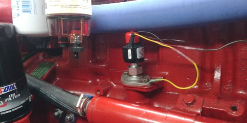
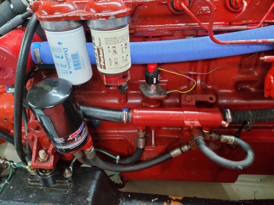
Since you have a Lehman 120, a more simple solution is to install a signal generator that puts out a constant number of pulses. Signal generators are commonly found. The generator in the picture is from Aetna Engineering. A signal generator paired with a programmable tach will yield a very accurate tach that never goes out of adjustment. You can using the existing supply wire to the tach and daisy chain from the lower helm to the upper helm if you have both. The signal generator will drive an original tach as well. 20201205_162925.jpg20210411_170438.jpg
 
Since you have a Lehman 120, a more simple solution is to install a signal generator that puts out a constant number of pulses. Signal generators are commonly found. The generator in the picture is from Aetna Engineering. A signal generator paired with a programmable tach will yield a very accurate tach that never goes out of adjustment. You can using the existing supply wire to the tach and daisy chain from the lower helm to the upper helm if you have both. The signal generator will drive an original tach as well.View attachment 133447View attachment 133448

If I had that option this is what I would do. This is how many aircraft engine rpm and turbo prop signals are generated. On aircraft the term used is Tach Generator. I am not sure if the design is the same but a tach generator and gauge is a stand alone unit. Meaning the tach generator not only provides the signal...but the power to operate the gauge. So during complete loss of power these gauges still run. Unfortunately on the newer glass cockpits the MFD needs back up power supply.
 
Piezoelectric sensor

I just got done figuring out a solid way to drive your old original alternator driven W signal tachometers from a hall effect sensor/magnet mounted to the front of the motor and signal adapter for around $110. Alternator driven tach signals are not the best and can be finicky. But many times people want to retain the original tachometer but use a different signal that might be more accurate and less finicky. I went through several variations before I settled on this one and I hope it will be reliable and accurate. Really you can use these two items to drive any tachometer. Its just been that W signal tachs have been harder to adapt. I made a video outlining all the details on how too and what items. Hopefully its useful to someone. I know I looked and looked and there was no clear roadmap if you wanted to retain your W signal tachs but use a better signal.


The Beta engine uses the output from the alternator’s field signal to provide the pulses to the the tachometer which is mounted on the engine control panel. This is fine, however when the battery is charged typically there will be no or little field voltage and therefore no tachometer readings. Other engines use a sensor mounted on the engine to count pulses from the engines flywheel. I found this problem rather annoying. I found a device made by Design Technologies in Indiana which senses the fuel pulses in an injector tubing with their piezoelectric sensor mechanically mounted to the injector tubing and electrically connected to their Piezoelectric Amplifier. That output signal drives the tachometer on the engine panel totally bypassing the problem.
 
The Beta engine uses the output from the alternator’s field signal to provide the pulses to the the tachometer which is mounted on the engine control panel. This is fine, however when the battery is charged typically there will be no or little field voltage and therefore no tachometer readings. Other engines use a sensor mounted on the engine to count pulses from the engines flywheel. I found this problem rather annoying. I found a device made by Design Technologies in Indiana which senses the fuel pulses in an injector tubing with their piezoelectric sensor mechanically mounted to the injector tubing and electrically connected to their Piezoelectric Amplifier. That output signal drives the tachometer on the engine panel totally bypassing the problem.

Thats what Tiny-Tach does as well. Thats what I had on the boat before this newer configuration and it worked well. But I had a sensor fail. I actually odered another to replace but also ordered the Hall effect sensors too just to experiment. I will use the hall effect sensor and see how the inexpensive units hold up. They were 4 for $12. The replacement piezo sensor was $75.
 
I just got done figuring out a solid way to drive your old original alternator driven W signal tachometers from a hall effect sensor/magnet mounted to the front of the motor and signal adapter for around $110. Alternator driven tach signals are not the best and can be finicky. But many times people want to retain the original tachometer but use a different signal that might be more accurate and less finicky. I went through several variations before I settled on this one and I hope it will be reliable and accurate. Really you can use these two items to drive any tachometer. Its just been that W signal tachs have been harder to adapt. I made a video outlining all the details on how too and what items. Hopefully its useful to someone. I know I looked and looked and there was no clear roadmap if you wanted to retain your W signal tachs but use a better signal.

Great video. I'm in and will be installing this solution.

Can I unplug the W wire from the alternator and connect (jumper) it to the output from the Dakota adapter? i.e. use the existing wiring.
 
Great video. I'm in and will be installing this solution.

Can I unplug the W wire from the alternator and connect (jumper) it to the output from the Dakota adapter? i.e. use the existing wiring.

Its been while now but im about 99.9% certain that's what I did. One thing I learned is if you have a tach that has full adjustability like the Aetna or any tach that has full adjustability you dont need the Dakota. If you have a tach that just has A, B, C, D etc you will need the Dakota.

Im actually sitting in the engine room doing other work so I snapped a pic of the bracket/magnets.
 

Attachments

  • 20240126_173903.jpg
    20240126_173903.jpg
    102.1 KB · Views: 47
  • 20240126_173913.jpg
    20240126_173913.jpg
    107.6 KB · Views: 49

Latest posts

Back
Top Bottom