Adjusting Fuel Cutoff Solenoid-HELP

The friendliest place on the web for anyone who enjoys boating.
If you have answers, please help by responding to the unanswered posts.
Joined
Jul 6, 2012
Messages
8,084
Location
USA
Vessel Name
Alaskan Sea-Duction
Vessel Make
1988 M/Y Camargue YachtFisher
Hey TF. I spend the morning with a Cummins Technician on the phone and he had me go through some steps It would seem my fuel cutoff solenoid is bad. Shorted to ground.

If you have been following us, you know we had a rough crossing over the Columbia River Bar. This put water into one of my cylinders causing a hydraulic lock. I pulled all the injectors (3 in all) and turned over the engine and blew out all the water. Put everything back together and it ran for 4 hours, but I had fuel all over everything, to include the fuel cutoff solenoid. This caused it to go bad.

Does anyone know the proper procedure to adjust the rod on this solenoid?:confused:
 
Did you check at the price f a replacement part? Diesel fluid solenoid should not be very expensive if m right, this may be easier.

Just a thought from a rookie :)

L.
 
Which model engine?
 
Onan


Model and Spec: 8.0 MDKD-3CR/26501B
Ser# I870947950


There is nothing in my manuals that show the adjustment procedures...
 
I hope you checked the crankcase oil for signs of water from the hydrolock....
 
Ok Tom, sounds like a new genny is on the wish list for next year, damn, and I thought a Auto Pilot would make the top of the list.

I am so glad we got "Otto" fixed, the admiral really talks sweet nothings to "Otto"
 
Adjust it so when it pulls across, it pulls across all the way. That way, once it starts, the "hold" is active, not the "pull across" bit. Unless it pulls right across it won`t start.
Where was all the fuel coming from?
The 2 problems I`ve had are:
1)the fuel solenoid. If it goes bad, replace it. I think the solenoid for MDKD and DKD is part 307-2546-00. (Cummins $300,Chinese version $60, Cummins one is made in China.)
2)The fuel filter not sealing in the housing it screws into, due to the housing being out of shape (?overtightening)= fuel everywhere. When I fitted the filter, and test ran it, dry as..next time, leaked copiously. Solution, new filter housing.
Some discussion about the solenoid is/was here: www.smokstak.com/forum/showthread.php?t=89089
 
On the MDKD, you adjust the fuel solenoid linkage so when fully retracted (energized), there is still some slop in the linkage. Plunger needs to fully bottom. It is not that important that stop lever be held firm against its stop.
 
Ok Tom, sounds like a new genny is on the wish list for next year, damn, and I thought a Auto Pilot would make the top of the list.

I am so glad we got "Otto" fixed, the admiral really talks sweet nothings to "Otto"

Otto is still sleeping. Should get part this afternoon. Yep I paid the Cummins price.

There is a cheaper china part? Figures

Thanks NC
 
I would change the oil, just in case. I did the same on my propulsion engine- hydrolocked it and squeezed the water past the rings with a bar over. After starting and running fine- no visible water but sodium in oil sample was 700 ppm. Should be less than 10.

David
 
I have an MDL3 using a Stanadyne DB2 injector pump, used in many diesels up to 8 cylinders. I've attached a couple of info sheets from Oregon Fuel Injection that may help. I also have a Stanadyne DB2 operation & instruction pdf that is over Trawlers size limit. Could be sent email.
 

Attachments

  • stanadyne-pump-diagnostic-troubleshooting.pdf
    499.2 KB · Views: 50
  • stanadyne-db2-db4-pump-removal-and-installation.pdf
    699.9 KB · Views: 85
I would change the oil, just in case. I did the same on my propulsion engine- hydrolocked it and squeezed the water past the rings with a bar over. After starting and running fine- no visible water but sodium in oil sample was 700 ppm. Should be less than 10.

David
Good point.
 
I have an MDL3 using a Stanadyne DB2 injector pump, used in many diesels up to 8 cylinders. I've attached a couple of info sheets from Oregon Fuel Injection that may help. I also have a Stanadyne DB2 operation & instruction pdf that is over Trawlers size limit. Could be sent email.
Thank you
 
Just curious, not familiar with how rough seas get water into engine, guessing from burying the stern in following seas when engine not running?
 
Does the water travel up the exhust or through the through hull pass the raw water pump?
 
I think up the exhaust which is why you want a loop.
But...this is "I think"....far from fact.

Ken
 
If engine is low, you want an anti-siphon loop in the sea water plumbing. Water will migrate slowly through water pump. Outlet of muffler should have loop going at least a foot above water line, more is better. Depending on the various elevations, water can get in through either path.

I recommend to my customers that when in rough stuff, leave gennie on. Water can't get in then.
 
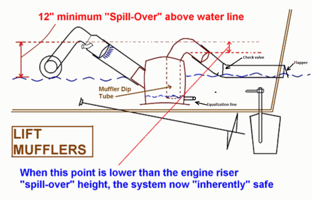
Exhaust system design is difficult. It is impossible on many boats to have an "inherently safe" system as defined by Tony Athens. You need two loops: one from the exhaust up and down to the lift muffler and one up from the muffler and down to the transom. The height of the second loop must be lower than the first. Otherwise repeated slugs of water coming up over that loop will fill the muffler and eventually fill the engine.

So most boats just use a high loop after the muffler and hope for the best. I had such a system on both the propulsion and genset engines on one of our sailboats, just like almost all sailboats. On one exhilerating passage with 25 kts of wind off of our stern quarter, enough slugs of water filled the muffler and flooded our genset engine.

The fix (other than rebuilding the engine as it was discovered too late to do any good draining the oil) was to route the exhaust out the side.

Here is Tony's pic of an inherently safe system:

David
 

Attachments

  • Tony's lift muffler design criterion.gif
    Tony's lift muffler design criterion.gif
    86.2 KB · Views: 42
So thanks to a suggestion to buy the solenoid outside the dealer, I looked at the solenoid and it is a Woodward Solenoid. This is a model 1502. I found this on their website:

Table 7. Linkage Adjustment
Step Action

1​
Examine the linkage and look for signs of corrosion, rust, oil and dirt, all of
which can contribute to unacceptable performance of the solenoid. Make
sure linkage moves freely without binding. If the linkage feels tight, check
for bent linkage, misaligned bracket, improper spring on control lever,
swivel head hitting control lever, etc. Loosen linkage as needed.
The linkage and the plunger must all move freely with your fingers.

2​
Turn the Key Switch to “Run/On” position.

NOTE:​
Take precautions during these checks to prevent pull coil burnout.
For internally switched solenoids, manually push the linkage all the way in.
The plunger should hold in place. If the plunger does not hold in, measure
resistance across the positive and negative terminals. The reading should
match the hold coil resistance listed in the Solenoid Coil Resistance
Check section. If the reading is not correct, the plunger is not activating
the internal switch and linkage adjustment is too short. Adjust linkage until
the plunger holds in.

For externally switched solenoids, manually push the linkage as far as it
will go. The plunger should hold in place. If the plunger does not hold in,
linkage adjustment is too short (for push type solenoids the linkage
adjustment is too long). Adjust linkage until the plunger holds in.

3​
Manually move linkage from shutdown to maximum fuel, ensuring
solenoid spring will return linkage to shut down position and full travel of
linkage is smooth, uninhibited, and does not exceed specified stroke.

4​
When a connecting rod is used, the stroke is adjusted by turning the rod
on its threads and locking the rod in place with a lockwasher and nut. The
solenoid should be energized during this adjustment. Use this procedure
with ES solenoids only if the linkage length is incorrect.

5​
When bead chain or cable is used, the solenoid should be energized and
the bead chain or cable length adjusted to give the desired lever position.
Plunger travel must be checked, especially when a bead chain or cable is
used in a connecting device. The plunger travel must be limited to the

solenoid’s rated stroke when it is de-energized. An “L” bracket can be
used to limit the plunger travel.​
 
I recommend to my customers that when in rough stuff, leave gennie on. Water can't get in then.

This is now my new standard in rough seas. This was the first time this has happened to me.:thumb:
 
This is now my new standard in rough seas. This was the first time this has happened to me.:thumb:

That is very good advice. When the incident described above occured we were on a 24 hour passage from Block Island to Cape May in those 25 knot winds. About half way through the passage, the batteries were getting a liittle low, so I started the propulsion engine which had a 120 amp alternator with external regulator on it to recharge the batteries for a couple of hours.

That action apparently saved the propulsion engine which had essentially the same exhaust geometry as the genset. I even thought about also starting the genset for a few minutes to blow out any water that got up over the loop into the muffler but I knew I had a high loop after the muffler so all would be good. I also thought about opening the drain on the bottom of the lift muffler but we were hanging on to a sleigh ride at that time, so that wasn't really practical.

I didn''t use the genset for several months after that trip and when I finally did start it it ran very rough- maybe a corroded valve or two that stuck open. Then pulled the genset and had the engine rebuilt.

We don't have the question of running the propulsion or genset engines on our trawlers since we run the propulsion engine to move the boat, so there is little reason to run the genset unless you like A/C.

But do run the genset in heavy fllowing seas or at least run it for a couple of minutes every hour or so to blow out any sea water that collects in the muffler.

David
 
From memory, the solenoid from Cummins was marked Woodward, made in China. The "non OEM" Chinese one I bought later, on ebay, on a tip from a TFer, is a spare onboard.
 
Exhaust system design is difficult. It is impossible on many boats to have an "inherently safe" system as defined by Tony Athens. You need two loops: one from the exhaust up and down to the lift muffler and one up from the muffler and down to the transom. The height of the second loop must be lower than the first. Otherwise repeated slugs of water coming up over that loop will fill the muffler and eventually fill the engine.

So most boats just use a high loop after the muffler and hope for the best. I had such a system on both the propulsion and genset engines on one of our sailboats, just like almost all sailboats. On one exhilerating passage with 25 kts of wind off of our stern quarter, enough slugs of water filled the muffler and flooded our genset engine.


The fix (other than rebuilding the engine as it was discovered too late to do any good draining the oil) was to route the exhaust out the side.

Here is Tony's pic of an inherently safe system:

David

I would question 12" as safe in a big following sea. Maybe per other comments just having everything running is best bet.

Edit: After second thought the concept of inherently safe is total BS. Shame on Tony if he used that language.
 
From memory, the solenoid from Cummins was marked Woodward, made in China. The "non OEM" Chinese one I bought later, on ebay, on a tip from a TFer, is a spare onboard.
I will be ordering some spares. My genny is up and running....
 
Back
Top Bottom