Battery bank wiring question

The friendliest place on the web for anyone who enjoys boating.
If you have answers, please help by responding to the unanswered posts.

Wdeertz

Senior Member
Joined
Jul 3, 2018
Messages
342
Location
USA
Vessel Name
Bagus
Vessel Make
Kadey Krogen 52-01
I'm putting together a 9 LFP battery bank. Each battery is 24V @ 50Ahr and will be wired in parallel. I've been searching online for the best way to wire this bank up. One method is for all 9 batteries to be wired parallel and the positive and negative loads to be drawn from opposite ends.

I've read on other online postings that its best to keep banks to no more than 3-4 batteries so my second option is to wire 3 batteries in parallel and connect to a bus bar and ensure the wire lengths/size are all consistent to ensure equal resistance. The LFP batteries have built in BMS so presumably the batteries should not get out of balance.

Does anyone see any pitfalls to the second option? Also, I'm assuming I could fuse after the bus bar (appropriate sized fuse for wiring), any issues with this? I've tried to draw a crude depiction of the two choices I am considering. Thanks
 

Attachments

  • scan.pdf
    402.7 KB · Views: 85
I like #2. I am doing a lithium bank of 3 Lion Energy batteries. They have removable posts so I am doing bus bars across the batteries instead of cables. It should make a cleaner install.
 
I like the 2nd approach because it'll make it much easier to quickly isolate a bad battery and get it (admittedly with 2 others) temporarily out of the (electrical) way by pulling the line to the + bus bar for that bank of 3.

Depending upon your battery box configuration, it may be possible to run straight across your pluses and minuses for each bank in opposite directions, without the wires looping pass the terminals. In other words, in your picture, run pluses from left to right horizontally across a row to the bus bar and minuses right to left horizontally to a bus bar, or vice versa.
 
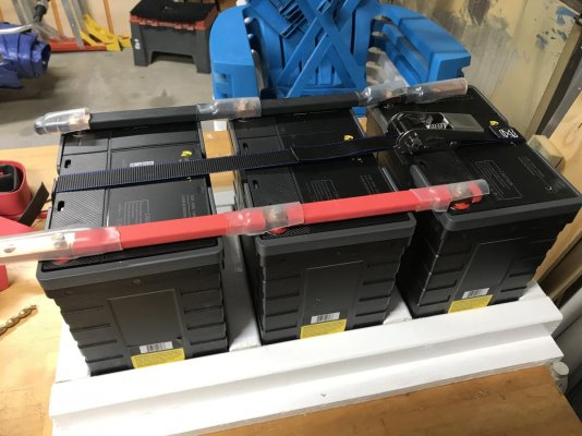
Here are my bus bars. I used heat shrink to insulate the bus bars and make terminal covers for the bolts.
 

Attachments

  • DCAEF4D7-8A5A-4F28-B735-153021E6D3BC.jpg
    DCAEF4D7-8A5A-4F28-B735-153021E6D3BC.jpg
    125.4 KB · Views: 37
  • 5EF19A37-ACB1-4CD4-AA80-6DC6DE282C61.jpg
    5EF19A37-ACB1-4CD4-AA80-6DC6DE282C61.jpg
    64.9 KB · Views: 31
Bus bars a more appropriate to connect banks of batteries however, I am curious on how you came up with 300A fuse!
Regards,
 
Blue Seas MRBF fuses go up to 300 amps. Just bolt the adapter to the bus bar and away you go.
 
Just so happens I am replacing all my batteries next weekend. The diagram on the left looks closest to being correct, but you don't show all your negative terminals connected together. If you want to keep it to code I believe the fuse needs to be within 7" of the battery.
 
Here are my bus bars. I used heat shrink to insulate the bus bars and make terminal covers for the bolts.

Thanks for sharing, I like your bus bars across the batteries, makes for a clean install with very little resistance. Unfortunately the batteries I am looking at don’t have top mounted terminals.
 
Bus bars a more appropriate to connect banks of batteries however, I am curious on how you came up with 300A fuse!
Regards,

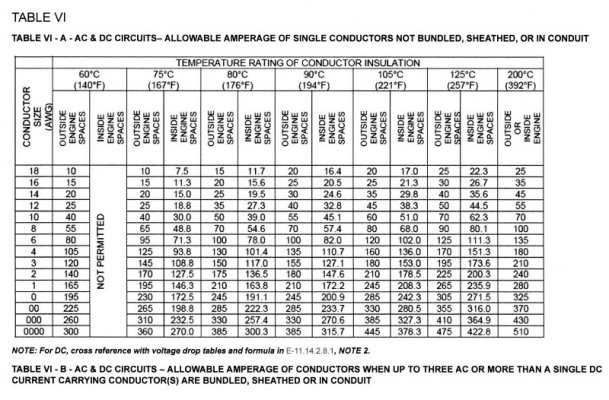
See attached ampacity table. 2/0 cables in 105c conductor outside the engine room have an ampacity of 330A. 300A fuses are easier to find and my max load will generally only be in the 200A range so plenty of headroom to avoid nuisance trips.
 

Attachments

  • A51771B3-CD3D-4A19-9BA8-1D9F4A8A8943.jpeg
    A51771B3-CD3D-4A19-9BA8-1D9F4A8A8943.jpeg
    130.8 KB · Views: 33
Just so happens I am replacing all my batteries next weekend. The diagram on the left looks closest to being correct, but you don't show all your negative terminals connected together. If you want to keep it to code I believe the fuse needs to be within 7" of the battery.

Russell, I thought I could save a few $$$ by leaving the negative cables off ?. In all seriousness I left the negatives off as it makes the diagram cleaner, isn’t it obvious the negatives would be connected?

As to the ABYC 7” rule there is an exception to 72” if the wire is in a conduit or sheathed.
 
I’ve placed my order for the 9 LFP batteries and will wire in parallel in banks of 3. I have a master shunt which all current will flow through so I’ll be able to measure the SOC for the entire bank.

Could I (or should I) get a separate, dedicated shunt on each 3 battery pack? That way I could use the master shunt to monitor the entire bank and these separate shunts for each 3 battery pack? In theory the 3 separate shunts should equal the one master shunt. Has anyone done this and is it worthwhile?
 
Here are my bus bars. I used heat shrink to insulate the bus bars and make terminal covers for the bolts.

Is that the battery tray too? What comes to mind is that cables will flex. Of course boats will pitch and roll. If the batteries are not locked down nice and tight, Will the buss bars but a strain on the battery post. Just a thought?
 
The batteries fit snugly into the tray, they don’t move at att. Also I have a S/S rachet strap that holds them down. I put them together before I put it in the boat. With it all assembled I couldn’t move any of the batteries at all.
 
I’ve placed my order for the 9 LFP batteries and will wire in parallel in banks of 3. I have a master shunt which all current will flow through so I’ll be able to measure the SOC for the entire bank.

Could I (or should I) get a separate, dedicated shunt on each 3 battery pack? That way I could use the master shunt to monitor the entire bank and these separate shunts for each 3 battery pack? In theory the 3 separate shunts should equal the one master shunt. Has anyone done this and is it worthwhile?


I don't have this problem but I think if you wish to monitor the banks individually to monitor actual charge/discharge balance then look into the Hall Effect ammeters from Amazon. The sensor simply slides over the wire, no cutting, no crimping, no extra connections and no extra Vdrop from any extra shunts. Just secure each of them with a couple Zapstraps.

They can be mounted on either the + or - lead but they also pick up polarity so which ever way you mount them be sure they are all the same to save confusion.

They do need a power supply, 12 or 24 V so consider arranging them with an on/off switch if you do not want the parasitic [ghost] load.

Even so the meters do have a +/- tolerance so they may not record exactly but should be good enough to see if one bank is way out of line.
 
Last edited:
Back
Top Bottom