Digital volt + amp meters

The friendliest place on the web for anyone who enjoys boating.
If you have answers, please help by responding to the unanswered posts.
Joined
Feb 24, 2008
Messages
681
Location
St. Lucia, West Indies
Vessel Name
"Dragon Lady"
Vessel Make
DeFever 41
Help from the electrically-minded please:

I have twin Yanmar diesels with the factory alternators. I want to install digital amp and volt meters so that I can see what the alternators are doing - especially at start up. Meter and shunt would be mounted in plastic box adjacent to each engine.

Would the meter in the pic and link below be suitable for my purpose?
Rating is 4.5-30v and 0-100 A.

Amazon.com: DROK® Voltmeter Ammeter Volt Amp Multimeter DC 4.5-30V 100A Voltage Currenr Monitor Ampere Testing Gauge V/A Panel Meter Red/Blue Dual LED with Current Shunt Car Auto Motocycle Battery Power: Home Improvement

T.I.A.
 

Attachments

  • Volt-Amp meter.jpg
    Volt-Amp meter.jpg
    42.8 KB · Views: 87
Doesn't look like it is designed to read amps coming off an alternator as like most ammeters reads off the negative pole such as that off a battery. Blue Seas makes a shunt shifter for this purpose which costs about 65 bucks. If it is going to mounted by the engine, why not just use a clamp meter for your amperage tests? An extremely useful tool to have on board regardless.
 
Last edited:
Do clamp on DC Amp meters really work? I have always used a shunt.
 
Clamp on DC ammeters work fine for diagnosis and testing. You can buy a cheap Chinese one for less than $75. But the one I bought as a spare has a lousy zero drift. When I turn it on it will read as much as 10 amps until I hit the zero button. That much drift makes me leery about its accuracy. But having used it for several things, both low and high amperage situations, it's accuracy is in the ball park after I zero it out. Most tests don't require absolute accuracy.


An Ancor meter I bought many years ago costs about $175 now, but it only has a few tenths of an amp drift when I turn it on. Fluke is one of the best, but about $300.


David
 
Correct me if I'm wrong, but looking at the schematic on the Amazon site, this unit is designed to measure the output of an alternator.

I wish it read higher than 100 Amps because it would be exactly what I have been looking for to have a meter at the helm showing volts and amps.

While a clamp-on amp meter would work if I went down into the engine room, I usually have other things to do when I first start up.

Ron, the Victron or Xantrex battery monitors will give you V and A plus battery charge as a %. My LinkPro will display voltage from both start and house battery banks, the current flowing in/out of the house and the % state of charge (SOC). IMO, the SOC is less than accurate and a Balmar Smartgage would be the perfect compliment to achieve the big picture monitoring needs.
 
Thanks Al, I do have a Magnum SOC that does all that but it is located at the nav station which is below the pilothouse, down a couple flight of stairs, so not very convenient. I would like something cheap at the helm so I can look at it when I start the engine.
 
Ron: If the meter proves to be suitable for this service, Amazon offers them with higher capacity by the same manufacturer.
 
Thanks Mike, I did find a 200 Amp meter. Are you going to get one of these? Seems like it should work for you.
 
Ron: Still waiting on more input from the electrically savvy.


The idea is to have them near the front end of the engines so I can include them in my regular after-startup rounds.
 
I bet this would work, but for how long? This auto/motorcycle unit may not hold up to the tougher environment found in marine service. I'd look at more 'fortified' units with sealed circuit boards intended for marine service. As a minimum, I'd consider sealing the circuit board with a product like CorrosionX.

 
Why not just use a State Of Charge meter designed for the boat and RV world?

That way you'll get amps, and volts, and know the state of your batteries all in one handy meter.

Pick your brand. I like the Xantrex Link Pro, but there are others.

Just a FYI, but it's a heck of allot easier to cut a round hole for an instrument than it it is to cut a square or rectangular hole. :)
 
Al: It is a concern, That is one of the reasons for mounting the meters in/on sealed plastic boxes.

Kevin: Thanks, but that's more sophiticated than I want to get. I'm a worrier and I want to reassure myself that my alternators are putting out, and how much. Square holes are (relatively) easy if you have a small vertcal mill.

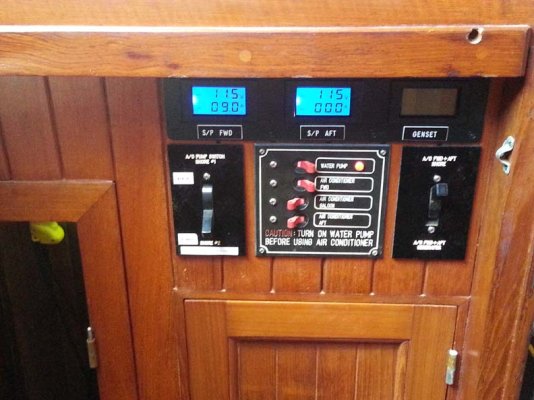
Generally I have had good experiences with a/c meters from the same mfg. The three in the pic show voltage and amps at the shore-power inlets and generator. The genset one only lights up when the genny is running.
 

Attachments

  • ac instruments.jpg
    ac instruments.jpg
    86.7 KB · Views: 87
No guys, all these you list are set up to measure the draw off the negative battery lead. Read the manuals and the specs! For the OP device "2.Current should be tested in the negative pole"

It is very easily be done, but you have to have the right stuff hooked up right. But why not just hook up the right meter to the battery in the first place? Think about it, and look at how +/- ammeters work, and higher end battery monitor kits

Shoalwaters, your OP says:
Meter and shunt would be mounted in plastic box adjacent to each engine.
, now you say by the helm... which is it?

Edit" looking further into the manual, it does look like the Blue Seas M2 is a +/- meter.
 
Last edited:
The Blue Sea meter has lots of bells and whistles and it costs nearly $240.00! All I want is an ammeter and volt meter telling me what my alternator is doing. I am not trying to monitor battery condition. Seems I can probably get that for around $20 per engine plus some time spent in my workshop.


George: I didn't say I want to mount the meters by the helm, someone else did.
 
Not sure why a clamp meter isn't OK. Once the engine is started, the alternator is working or not. If externally regulated adjust, if internal all you have is what you have. Yes you may have to check at cruising
RPMs.

Other than that..... in all my tens of thousands of hours underway....not sure it was an issue unless the belt broke or wasn't working from the very start.
 
The Blue Sea meter has lots of bells and whistles and it costs nearly $240.00! All I want is an ammeter and volt meter telling me what my alternator is doing. I am not trying to monitor battery condition. Seems I can probably get that for around $20 per engine plus some time spent in my workshop.


George: I didn't say I want to mount the meters by the helm, someone else did.

Are your tachs driven off your alternators?

I take it you have no amp or volt meters at all now? And no alternator idiot lights?
 
Last edited:
I find it essential to monitor electrical charges and voltages immediately after startup and include them in my normal engine instrument scan while underway. I've never found the need to monitor those values while in the ER.
 
The meter doesn't know or care whether the shunt is on the negative or positive pole. Whole house meters are usually on the negative pole because that makes it easier to measure everything in the system. For alternator or solar panel output, you can just put the shuntg on the positive side and be done with it. I have an amp meter on the positive feed of my alternator and it provides useful information (Like my voltage regulator is currently toast <g>).
 
To address your original question, it probably is not suitable for what you want it for unless your alternators have isolated grounds. If they do you can install the shunt in series in the ground circuit. If they are grounded through the case these meters would have to be connected in the battery ground cables and would indirectly show what the alternators are doing.
The voltmeter measures volts between positive and negative. The amp meter measures the voltage between one end of the shunt and the other. This meter assumes that one end of the shunt is grounded, which means it won't be suitable for alternator output unless the alternator has a separate and electrically isolated ground cable.
If you have a separate ground cable on the alternators and if there is no continuity between the alternator case and the ground terminal (with the ground cable disconnected from the terminal) then you could install the shunt in the ground circuit and the meter will show you alternator output.
Another alternative would be to use 2 independant meters, a voltmeter that you can switch between altlernators and an ammeter that you can switch between 2 shunts in the output circuits of the alternators.
 
SteveD
I would generally agree, except this manufacturer forces a common connection between the ground and one shunt terminal.
 
The low cost method might work for you.

While nothing beats a SOC setup perhaps this will do.

Simply install a pair of flush push in pin sockets on the dash connected to the start cable of each engine.

When interested ,plug in the VOM , observe the standing voltage and then observe the voltage while cranking.

The voltage rise after engine start will show the alt is working , and you can start the other engine.

This will catch a load of horrors like no starter cut out although it wont give the amperage of the alts.

For most the cost is very minor as most have a VOM already .
 
If you have a separate ground cable on the alternators and if there is no continuity between the alternator case and the ground terminal (with the ground cable disconnected from the terminal) then you could install the shunt in the ground circuit and the meter will show you alternator output.

I have just checked with the continuity function of my multi-meter. The ground terminal is isolated from the case of the alternator. Digital amp/volt meters on order. Will post results when installed. Thanks all.
 

Attachments

  • Ground pin.jpg
    Ground pin.jpg
    102.8 KB · Views: 66
The meter doesn't know or care whether the shunt is on the negative or positive pole. Whole house meters are usually on the negative pole because that makes it easier to measure everything in the system. For alternator or solar panel output, you can just put the shuntg on the positive side and be done with it. I have an amp meter on the positive feed of my alternator and it provides useful information (Like my voltage regulator is currently toast <g>).

FWIW, I completely agree with this. The shunt doesn't know and doesn't care where in the circuit it is. It just knows that electrons are flowing through it and it counts, etc., those electrons. If it has the capacity, it will work. If it doesn't get a bigger one.
 
Correct in principle. However take a look at the specs on this unit. It only uses 3 wires and one end of the shunt has to be grounded. Placing it in the positive side of the alternator and connecting the wires as directed may cause a dead short to ground with associated smoke and melting wires.
 
Correct in principle. However take a look at the specs on this unit. It only uses 3 wires and one end of the shunt has to be grounded. Placing it in the positive side of the alternator and connecting the wires as directed may cause a dead short to ground with associated smoke and melting wires.

Grabbed this off the web site. It made it very easy to understand:

I wired mine in between the batterie negative to the chassis ground And wired all of my electronics to chassis ground

By Stephen meagher on August 31, 2015:
The black and yellow wire connect across the shunt with the black lead on the most negative side. The red wire must be connected to a positive voltage between 5 and 30volt all 3 wires are only voltage sense and carry NO current.

The wires are very flimsy so strip with care.
 
It's not the current shunt that makes you use ground as one of the connections, it's the volt meter that reads the voltage across the shunt that is the issue here.

A shunt is nothing more than a device that takes produces 50 milivolta at it's rated current. Nothing more than a resistor.

The meter part is nothing more than a volt meter that you think is reading out in amps. In reality the meter is a 50 milivolt volt meter.

If the sensing inputs are isolated from ground then you can use the shunt any place in the DC current path. If the sensing inputs are not isolated then you'll need to install it referencing ground, which limits your options.
 

Latest posts

Back
Top Bottom