I am trying to verify the operation of my 1979 Ocean Trawler water level gauge and sender.
It is a VDO, 1979 era.
I attached pictures of a similar gauge's diagram, the gauge, and the sender.
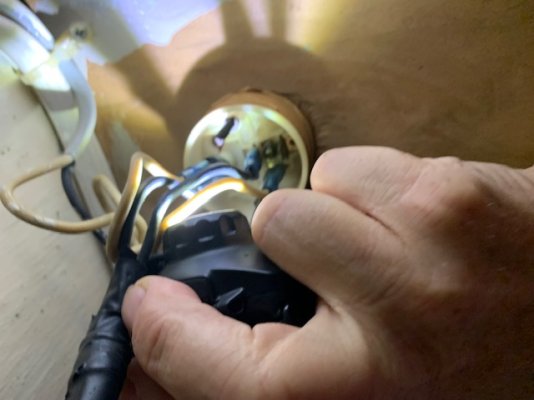
1. The terminal configuration on the back of the gauge is like the 3rd version shown on illustration D on the provided diagram. I also provided a picture of the back of the gauge. I believe the "+" (power) connector is parallel to and next to the side of the instrument, the "s" (signal) connector is parallel to the "+" connector but further from the side of the gauge, and the "-" (ground) connector is perpendicular to the side of the instrument.
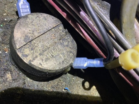
2. As best I can determine the numbers on the top of the sender are: 40/187 and 878/1/1. There is a third number that I cannot read.
I could not find a company name on the sender.
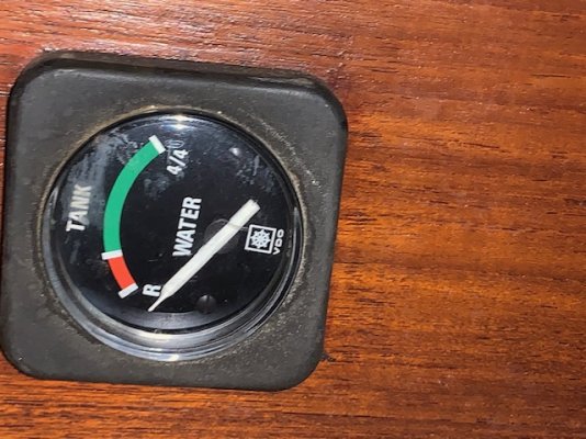
Initially the sender wire was disconnected. When I reconnected it to the open connector, the needle went hard to the right - past the full mark. I thought the power and sender wires might be reversed, so I switched them and the needle moved smoothly to the full position. Alas, my water tank is only about 1/2 full.
I tested 183.5 ohms across the two blade connectors on the sender and 184.6 ohms across the sender wires while disconnected from the gauge, so I think the wires are good.
If the 40/187 numbers on the sender are its resistance range in ohms, my 183.5 ohm measurement would correctly read "full" on the gauge. If my tank is actually 1/2 full, that would mean the sender is stuck in the "full" position.
So, I suspect the sender is bad and need to verify the resistance range of the gauge and sender, so I can match a replacement sender to the gauge, or I will have to replace the whole system.
Is it likely the resistance range is 40-187 ohms?
Any help would be appreciated.
It is a VDO, 1979 era.
I attached pictures of a similar gauge's diagram, the gauge, and the sender.
1. The terminal configuration on the back of the gauge is like the 3rd version shown on illustration D on the provided diagram. I also provided a picture of the back of the gauge. I believe the "+" (power) connector is parallel to and next to the side of the instrument, the "s" (signal) connector is parallel to the "+" connector but further from the side of the gauge, and the "-" (ground) connector is perpendicular to the side of the instrument.
2. As best I can determine the numbers on the top of the sender are: 40/187 and 878/1/1. There is a third number that I cannot read.
I could not find a company name on the sender.
Initially the sender wire was disconnected. When I reconnected it to the open connector, the needle went hard to the right - past the full mark. I thought the power and sender wires might be reversed, so I switched them and the needle moved smoothly to the full position. Alas, my water tank is only about 1/2 full.
I tested 183.5 ohms across the two blade connectors on the sender and 184.6 ohms across the sender wires while disconnected from the gauge, so I think the wires are good.
If the 40/187 numbers on the sender are its resistance range in ohms, my 183.5 ohm measurement would correctly read "full" on the gauge. If my tank is actually 1/2 full, that would mean the sender is stuck in the "full" position.
So, I suspect the sender is bad and need to verify the resistance range of the gauge and sender, so I can match a replacement sender to the gauge, or I will have to replace the whole system.
Is it likely the resistance range is 40-187 ohms?
Any help would be appreciated.