Marco Flamingo
Guru
- Joined
- Jan 7, 2020
- Messages
- 1,173
- Location
- United States
- Vessel Name
- CHiTON
- Vessel Make
- Tung Hwa Clipper 30
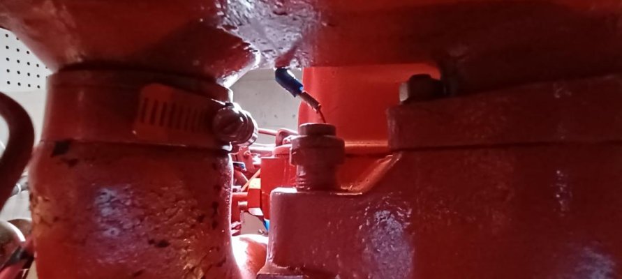
I'm trying to troubleshoot why my overtemp idiot buzzer isn't working. Best I can tell from my investigation to date is that the ignition circuit breaker energizes the oil pressure buzzer (normally closed and open with pressure to stop the buzzer) and the overtemp buzzer (normally open but closes at 205F to activate the buzzer). That is what I thought I would find. So the wire to the overtemp sensor (left side of engine under the coolant reservoir) would be 12V hot, closing the sensor would complete the circuit by grounding, and the buzzer would go off. Picture below.
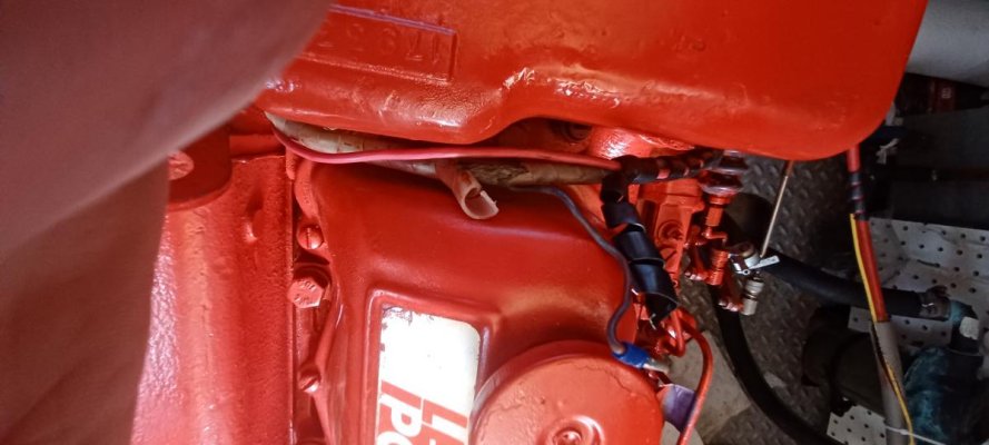
What has me confused is that the wire to the temp sensor is simply soldered to a braided wire, covered (sort of) by a plastic wrapping. Picture below. I haven't tested it yet with a multimeter, but I can't believe that that poorly insulated braided wire draped over the engine is 12V hot and that's what provides 12V to the NO sensor.
Am I missing something on how the overtemp buzzer works (when it works)?
Mark