Location of anti-siphon valve in raw seawater cooling system

The friendliest place on the web for anyone who enjoys boating.
If you have answers, please help by responding to the unanswered posts.

TristanJ

Member
Joined
May 28, 2024
Messages
6
Location
Australia
Hi everyone, got a possibly very straightforward question here for the cooling systems experts. I have a 40' timber vessel with a Perkins 6.354 upright non-turbo engine and I'm doing a bit of a refit. My question relates to whether I can change the position of my raw seawater cooling anti siphon valve as the current setup is cumbersome. Basically, I'd like to know if anyone sees a problem with me putting in directly after the raw seawater pump instead of directly after the exhaust manifold cooler (see block diagram below (existing setup on the left, proposed on the right).

Extra info is that the engine is predominately below the waterline, the apex of the anti siphon valve is 400mm above the waterline, there is a raised loop between the exhaust manifold cooler and the water / gas mixing point, and a raised loop at the stern of the vessel right before the exhaust passes through the hull.

Perkins 6.354 cooling diagram.drawio.png
 
If you are confident in the raised loops after the pump, I cannot see a big problem with your idea.
 
The only thing I see is that there is a larger quantity of water between the loop and the exhaust elbow, so the possibility of more water that could find its way to the elbow. So I would look at how much water that is, and whether it might be an issue.
 
Placing the anti-siphon valve legs after the coolers CAN be an issue as follows. I had a case where my small generator's one-inch ID exhaust line was directed upward by about nine inches from the where the exhaust line came out of the bottom of the generator's skid which was also right near the waterline. The installation team at the factory was too lazy to drill a hole in the bulkhead (as had been done in other boats of the same model) separating the genny and the lift muffler and so directed the exhaust line over it and then down to the muffler whose base was at the same level as the bottom of the generator's skid. Every time the genny was shut down, water left in the nine-inch rise fell back toward the engine whose head was only a couple of inches or so above the bottom of the skid. The anti-siphon valve was set up between the exhaust/water mixing point and the outlet of the cooler which meant that water from one leg of that anti-siphon vent was also contributing to the water collecting in the bottom of the exhaust line causing corrosion in the head and cylinder of the engine. It took less than a year for the head and valves to get rotted out to the point there was no compression.

While forced to moor the boat in the water for a year while its lift had hurricane damage repaired, wave action from a storm pushed water back through the muffler to hydrolock the genny despite the over one-foot rise of the exhaust line out of the top of the from the lift muffler. The anti-siphon installation placed where it downstream off the cooler was not designed to handle that sort of intrusion and was really there to prevent siphoning through the system from the seawater intake side, but the impeller pump would probably stop that anyway. To prevent similar hydrolocking in the future in the event of the boat being moored in the water rather than its lift, I installed a Centek exhaust line flapper valve.
Centek check valve (2).JPG
 
The only thing I see is that there is a larger quantity of water between the loop and the exhaust elbow, so the possibility of more water that could find its way to the elbow. So I would look at how much water that is, and whether it might be an issue.
I agree with this.

I want the least amount of water possible in the lift muffler.

Something I added to both the engine and generator lift mufflers were quarter turn drains. It's very easy to forget about water filling the lift muffler, when the engine doesn't immediately start, and you're trying to figure out why. My procedure was to open the drain valve on anything but an immediate start. You can always go back down and close the valve once the engine is running.

Ted
 
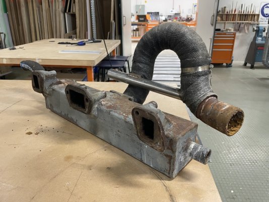
Thanks @rgano and @twistedtree for your replies, further to my post, here is a photo of my exhaust manifold with the raw water injection point after the 3” riser loop. The original anti-siphon valve was plumbed between the 1-1/8" outlet at the bottom right of the photo and back into the stainless steel 1-1/8" pipe where it was injected into the exhaust gas flow after the riser loop. I don't know exactly where the apex of the riser loop sits in relation to the loaded water line, but in my way of thinking two things come to mind:

1. I suspect that the existing anti-siphon valve was installed to prevent water flow continuing in the normal direction (from the strainer), in which case it is absolutely fine to move it upstream (and probably better as outlined here: chrome-extension://efaidnbmnnnibpcajpcglclefindmkaj/https://www.northern-lights.com/media/PDFs/misc_pdfs/dont_drown_me.pdf), and

2. No pissy little 1-1/8" anti-siphon valve is going to do anything to stop the torrent of water travelling up a 3" bore exhaust and back into the exhaust manifold especially if it located after the merge point (in relation to water being pushed back into the exhaust outlet). The 3" riser loop (shown in the photo) along with the 3" riser loop in the transom should provide the protection required, but perhaps adding a flapper valve at the exhaust outlet would also be wise?

Thoughts?

Cheers!!!
 

Attachments

  • IMG_7123.jpeg
    IMG_7123.jpeg
    171.6 KB · Views: 7
Last edited:
The only thing I see is that there is a larger quantity of water between the loop and the exhaust elbow, so the possibility of more water that could find its way to the elbow. So I would look at how much water that is, and whether it might be an issue.
I suspect it will be minimal as the pipes will be 1-1/8" and I suspect that when the engine stops and the columns of water fall from the anti-siphon valve it would likely only be less than a litre that would be added on the downstream side. I suspect this should easily be accommodated by the muffler pot.
 
Thanks @rgano and @twistedtree for your replies, further to my post, here is a photo of my exhaust manifold with the raw water injection point after the 3” riser loop. The original anti-siphon valve was plumbed between the 1-1/8" outlet at the bottom right of the photo and back into the stainless steel 1-1/8" pipe where it was injected into the exhaust gas flow after the riser loop. I don't know exactly where the apex of the riser loop sits in relation to the loaded water line, but in my way of thinking two things come to mind:

1. I suspect that the existing anti-siphon valve was installed to prevent water flow continuing in the normal direction (from the strainer), in which case it is absolutely fine to move it upstream (and probably better as outlined here: chrome-extension://efaidnbmnnnibpcajpcglclefindmkaj/https://www.northern-lights.com/media/PDFs/misc_pdfs/dont_drown_me.pdf), and

2. No pissy little 1-1/8" anti-siphon valve is going to do anything to stop the torrent of water travelling up a 3" bore exhaust and back into the exhaust manifold especially if it located after the merge point (in relation to water being pushed back into the exhaust outlet). The 3" riser loop (shown in the photo) along with the 3" riser loop in the transom should provide the protection required, but perhaps adding a flapper valve at the exhaust outlet would also be wise?

Thoughts?

Cheers!!!
Hi @twistedtree and @rgano , do you have in issue with my understanding in the above two points?
 
Back
Top Bottom