MS 390 shore power 30 amp outlet not working

The friendliest place on the web for anyone who enjoys boating.
If you have answers, please help by responding to the unanswered posts.

Lshulan

Senior Member
Joined
Jan 10, 2022
Messages
156
Vessel Name
Voyager
Vessel Make
Mainship 390
One of the 30amp outlets on the bow is not working, the other is fine as are the two at the stern. I’m very familiar with the breakers at the electrical panel to select which outlets are being used so I don’t think the problem is there. I’ve tried several shore power cords that are known good and that’s not the problem. I tripled checked the breakers at the bow, are there any other obvious things I should look for? Can anyone suggest how I go about trouble shooting this?
 
Have you checked the inlet in question for heat damage? It can happen easily due to corrosion on the contacts and then the added resistance causes the connection to heat up. Simple solution is to replace the inlet. If the inlet looks good then get your multi meter out and ohm the 3 wires from the inlet to the panel inside and make sure all 3 have continuity. It could be the selector switch that lets you choose between bow inlets and stern inlets.
 
Have you checked the inlet in question for heat damage? It can happen easily due to corrosion on the contacts and then the added resistance causes the connection to heat up. Simple solution is to replace the inlet. If the inlet looks good then get your multi meter out and ohm the 3 wires from the inlet to the panel inside and make sure all 3 have continuity. It could be the selector switch that lets you choose between bow inlets and stern inlets.

In agreement here. Bet you find the wire burnt off the back end of the socket.

If it isn’t burnt then the Best diagnostics would be to take a multimeter and look for voltage between the black and white wire. Test at the back of the socket and then follow thE wire until the voltage disappears.
 
Thank you both for your helpful info, will check the back of the outlet tomorrow. Unsure of the diagnostics tiltrider1 suggested, can you elaborate step by step? Ie, do I remove the plug so as to access the back, plug it in to a live shore power cord and test, is that what you mean since im not sure where it would get any voltage otherwise.
 
If you can not access the back of the plug from inside the boat you will need to remove the plug attachment screws so you can pull the plug out of the wall. Then put one probe on the black terminal and one on thE white terminal. Yes, the shore power plug will need to be attached so do be careful. If you find voltage here then move to the master circuit breaker and measure for voltage on both sides of the circuit breaker.
 
Not trying to be nasty but if you need this explained then you should probably get a certified marine electrician to come help you. If you aren’t knowledgeable about AC electrical work it can be dangerous, even deadly.
 
Thanks tiltrider1, that’s what I thought, just wanted to make sure we were on the same page. I’ve worked with both ac and dc circuits many times and therefore I wouldn’t have any issues with such a simple check. I will add pulling the circuit breaker that’s above the outlets and test there as well before moving to the main ac panel - hopefully a badly burnt outlet! Will update tomorrow or next day
 
Thank you both for your helpful info, will check the back of the outlet tomorrow. Unsure of the diagnostics tiltrider1 suggested, can you elaborate step by step? Ie, do I remove the plug so as to access the back, plug it in to a live shore power cord and test, is that what you mean since im not sure where it would get any voltage otherwise.

DO NOT try to test this with live power! It is pretty clear from your post that you don't have a thorough understanding of electricity.

Disconnect all power to the boat and then check for continuity with an ohm meter (or a tester set to measure resistance or continuity).

Probably the safest thing to do is to hire a competent marine electrician. This should be a quick and simple diagnosis for an experienced pro.
 
I use a simple process of elimination to trouble shoot this stuff. Start at the beginning and then check for power or functionality down the line. That said, tongue in cheek, almost always the problem is at the end of the line and requires the most expensive part to be replaced LOL:). So, I always jump to that part to start now!
 
I use a simple process of elimination to trouble shoot this stuff. Start at the beginning and then check for power or functionality down the line. That said, tongue in cheek, almost always the problem is at the end of the line and requires the most expensive part to be replaced LOL:). So, I always jump to that part to start now!

That is brilliant, you must be a Murphy's Law School alum.
 
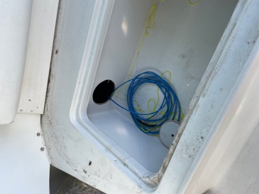
This is the hole I put in. The yellow string is pull lines , one to the flybridge console and the other to the salon console so if I need to pull any more cables it is very easy using the pull lones.
 

Attachments

  • IMG_0411.jpg
    IMG_0411.jpg
    56.4 KB · Views: 32
  • IMG_0412.jpg
    IMG_0412.jpg
    52.7 KB · Views: 28
Turns out 2 problems, fixed the first one. The hot and common leads weren’t very secure, simply tightened them and now the inlet works, very simple, and I feel dumb for not checking first, assumed PO would have checked. But now a second problem related. Background, I only have one 30amp dedicated outlet on my dock and in process of adding a second one but in meantime, using a 15amp GFI outlet on dock with a pigtail. When both connected, the 15amp GFI trips but with only that 15amp connection, it works without tripping. So it would seem to me that the 30amp connection (could be the dedicated outlet or its associated wiring or perhaps on the boat) is the issue. My question is does having BOTH connected somehow have the gfi sense an imbalance, ie, once both connected, does the panel mix them together?
 
Check the panel configuration. If it has common neutral then the imbalance can cause a GFCI trip. Even if separate neutrals the 20A receptacles have a lower threshold than a 30A one.
With your description it would point to a common neutral and imbalance.
I beluieve that if you experience the same issue with a second 30A source you may need to separate the neutrals.
 
Last edited:
Don - thank you for the thoughtful response, I believe that may be the issue. In meantime, I looked up online the electric code and while some mixed responses, it appears that a gfi is not required in a 30amp dedicated circuit so once I get the new 30Amp circuit installed , this may be a moot point. The 110 outlets are gfi protected so I think I really don’t need gfi anyway in the 30 amp inlets

Thanks to all
 
GFI requirements vary vased on applicable code when installation/ major renovations occur. Some marinas will claim "maintenance" even when doing refurbishment. A new installment will definitely require GFCI on 30A as well as 50A.
When our marina was rebuilt and all new elec service installed, 20A, 30A 120V & 50A 240V, all have protection. It took the contractor over a year to get them straightened out as breakers had to be configured using a laptop and included over current, GFCI limit and time delay. All different for pedestal, distribution panel / circuit breakers and main breaker.
 
I believe that the latest version of the NEC also requires it on residential docks not just marinas.
 

Latest posts

Back
Top Bottom