Need help and advice - new issue with shaft seal

The friendliest place on the web for anyone who enjoys boating.
If you have answers, please help by responding to the unanswered posts.

Lou_tribal

Guru
Joined
Jan 20, 2016
Messages
4,391
Location
Canada
Vessel Name
Bleuvet
Vessel Make
Custom Built
Hi TFers,
Again another day, another pain.
This morning when checking the shaft seal I found out something odd.
As I am not used to these seal I request your knowledge and help here.
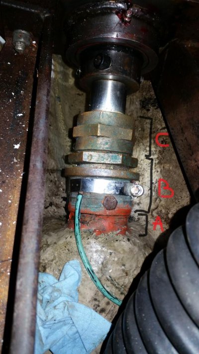
Here is a picture of my seal:

20170613_121357.jpg

It is a packing gland as seen on picture. My issue is that the part that goes on the hull (the one with the grounding wire on it) is loose. I mean I can turn it with one hand, not totally loose but moveable. I don't think this is normal ???
If I put my hand under and touch with my fingers I can feel that some (few but some) water can pass there and again I think this is not normal as if I am right the water drops should only goes along the shaft through the packing nut.

May yu please advise if there is any danger there, should I haul out? I start to be a bit desperate, looks like this year I am not due for vacation :nonono:

Thank you in advance.

L.
 
It looks like you have a very short piece of rubber hose, about 2-3" long between the fiberglass nipple? and the packing gland. There is a hose clamp on the packing gland, but I only see a hex bolt head on the nipple end. Usually the hose is much longer, about 6" and has hose clamps on both ends and usually in pairs on each end.

So I can't see what is holding the hose to the nipple other than that hex bolt which is rather weird. Or maybe I am seeing the picture wrong. The pic below shows the more common installation of a packing gland.

David
 

Attachments

  • packing gland.png
    packing gland.png
    95.9 KB · Views: 557
It looks like you have a very short piece of rubber hose, about 2-3" long between the fiberglass nipple? and the packing gland. There is a hose clamp on the packing gland, but I only see a hex bolt head on the nipple end. Usually the hose is much longer, about 6" and has hose clamps on both ends and usually in pairs on each end.

So I can't see what is holding the hose to the nipple other than that hex bolt which is rather weird. Or maybe I am seeing the picture wrong. The pic below shows the more common installation of a packing gland.

David

Thank you very much David.
There is no hose, the bronze part comes over the fiberglass nipple and there is a bolt going through the bronze and fiberglass to keep it in place (a bit odd no?) The clamp you can see is only used to fix the bonding wire tight on the bronze part.

L.
 
Long story short-ish.

We had to change the packing gland when the boat was in the water once. I was amazed at how little I had to tighten things to stop the flow of water. If it's just dripping water a couple times a minute under way, that's okay. Keep peeking at it for the first while as you may have to tighten it up later.

Others with WAY more experience than I may not agree......

Thank you Murray. Currently it is dripping 1 drop every 2 second to 5 seconds nothing that the pump cannot handle. My concern is more about the bronze piece on the fiberglass thruhull that is not tight, it makes me a bit nervous after what we experienced yesterday (see other post about it).
One guy working here told me that there is no danger of something that would break apart just that it will drip a bit more in the bilge but I can make the repair later. Just want to be sure about it.

L.
 
That entire assembly looks suspicious. I have this feeling it is just waiting for something to go seriously wrong. The stuffing box appears conventional but the attachment/connection to the shaft log does not look "standard" to me unless something just isn't apparent.
 
Lou:

Ok, I understand, no hose. So I suspect that originally there was sealant between the bronze and the nipple. There is probably more than the one bolt that you can see from the pic holding the bronze gland to the nipple. I would suspect three.

If that is the case, then movement of the bronze to the nipple over the years has broken the seal and lets it drip. I don't think that it can be made like my pic- there isn't enough room for a longer hose and the bronze is too big anyway for a hose to fit the outside of the bronze and the outside of the nipple.

But it may not be a catastrophe waiting to happen. Try working some 4200 inside the bronze to nipple joint with yur finger to seal up the small leak. Then the next time you haul, pull it off, clean up the joint and seal it up tight with 5200.

David
 
Greetings,
Mr. L_t. What I see in Mr. dj's picture is what I have always known to be called a "self aligning stuffing box" where the rubber tube allows a bit of misalignment due to the flexibility of the rubber tube. One end of the rubber tube is clamped to the actual stuffing box and the other end is clamped to the shaft log.

What I see in YOUR picture is a stuffing box attached directly to the shaft log. no rubber tube. So what moves (what part can you turn with your hand)? The flanged fitting immediately forward of the clamp or the fitting that's red with the hex nut on it immediately aft of the clamp?

IF you can't turn the bronze piece that's painted red, I agree with Mr. dj as to the construction and his opinion that it may not be a catastrophe. IF you can turn the red piece with your hand, I'd stay home and drink all your wine.
 
Last edited:
Is that rusty bolt the original grounding place or is it to keep the nipple from turning . Is that a pipe nipple attached to the shaft log? Could he just take out he rusty screw and pump some thread sealant like teflon and tighten up the bronze piece on the nipple ?
 
Fully agree with RT: If you can turn the red piece ... seal lost connection to stern tube. Not good, haul out.
Crossing fingers I'm wrong.
 
Fully agree with RT: If you can turn the red piece ... seal lost connection to stern tube. Not good, haul out.
Crossing fingers I'm wrong.
Yes for sure . I was thinking it was just loose on the thread .
 
... or is the red piece the stern tube itself, but has it lost tied connection to the hull?
If so, would it improve the situation?

I'm not familiar with such a design. IMO a shaft seal should be bolted to e.g. a floor timber to avoid any movement. Seems the red piece here is just fitted into the laminate.
 
To clarify things, here is the same picture annotated:

annotated_stuffing_box.jpg

Part marked A is the hull part, in fiberglass that comes in part marked B which is in bronze. This bronze part has a nut on the top that goes into part A. I checked and I can slightly turn part B (half a inch in each direction) few drops of water can find their way when I move it like that.
Part C is the nuts containing the packing that is screwed onto part B.

One of the guy at the marina went to check and told me that the packing inside the nut needs to be serviced but it still fine and this can wait. For the Part B that is moving same he told me that it will need to be serviced but there is no immediate danger of anything breaking apart.

Any thought?

L.
 
Greetings,
Mr. L_t. Well, IF part A is not moving at all the last mechanic is possibly correct. It's REALLY difficult to give you a proper and correct answer. All of the suggestions so far have been pretty good but none of us are there. I guess the ultimate decision is up to you sir.
 
If A is made of fiberglass (correct?) I would expect it is the stern tube, in which B is fitted in and held by the bolt (with the hex) which should retain the shaft seal (B+C) from any movement.
But you have a movement in circumferential direction. Issue, but might not be more and might wait until next haul (winter).

But: Can you move it in axial direction?
If not and leakage is only some drops when moved circumferentially I would monitor it when under way and decide upon observed progress of leakage.
If yes, I would haul now.

B might also be a radial shaft bearing (although pretty short) but wouldn't change my decision.
 
Looks like lock nut is backed off. Can't really comment on the stuff aft of that.
 
Is A a male thread and B a female thread that connects to A ? If it is is it leaking Ithru the threads ?
 
Thanks guys, as I am concerned and it is not my style to play with safety here is my plan. I will do a test run tomorrow around the marina and will monitor how it behaves. If I feel not secure going like that I will ask the marina to haul me out, will remove the nut and slide the assembly out of the stern tube and give it a check. If the tube is not damaged I will use 4200 (5200?) to seal it and put the assembly back in place. If I do that I will also take the opportunity to repack the gland so it is done.

Thank you all again, your input has been very valuable and much appreciated.

L.
 
Out of curiosity, how old is the boat (and the install)? Hours?
 
Looks like lock nut is backed off. Can't really comment on the stuff aft of that.

Agree, lock nut should be tight up against packing nut.

The stuffing box with the red end is ribbed indicating it was designed to fit into a tube. Someone tried to fit 18" of hardware into a 12" space.
The hex bolt may have been threaded into the shaft tube and somehow sheared?

If the prop is a loose fit in the shaft log I would think water ingress would be more than a drip or two. Don't think I'd make any blue water passages with it.

Indeed I found odd that the stuffing box with has the barbs that indicates it should have been fitted in a hose. The prop in the shaft log is not loose, I checked it when I was on the hard and it was really not moving anyway, I also tried to move it to see if there is any movement of the shaft possible and it looks like it is tightly fitted.
The guy who built this seems to have done a correct job even if it may look unconventional. For example from transmission to shaft here are 2 universal joint (is it the correct word?) a bit like what can be seen on trucks as you can see on the following picture (forget the wire I was rewiring my bilge pump).
I have been told this is uncommon on boats, is that right?

IMG_20170507_134931.jpg

L.
 
It seems to me that if you put a hose clamp in front of position C, in case the large nut, which appears to not be locked, moves, there is nowhere that that assembly can go unless it seizes and that bolt lets go and it spins. It might let in a bit of water but it doesn't appear to be a fatal.

In a conventional shaft seal, leaks can develop in the packing, too tight a packing can score the shaft making leaks impossible to stop or the main nut can back off letting the packing move and causing a leak. Also, some people use carbon-based packing which can eat the shaft tube if its aluminum (I'm not sure about bronze but I have my doubts) as carbon is right at the most active end of the galvanic scale.

Your shaft seal has a shaft bearing very close to it so there is no alignment issues possible.

Also, hose clamps to connect bonding straps (wires) like you have is a very poor way to do bonding. You "might" get away with it because it looks like you are not in salt water.
 
I think I'd get after that right away, this could be a disaster about to occur!
The stuffing box was never intended to be installed like that, there is supposed to be a rubber hose between A and B, to allow flexibility and be "self aligning".
I can see that the installer simply ran out of room, and decided to skip the rubber part.
The motion and vibration of the shaft is likely hogging out the fiberglass under the set screws, and in due time may cut the stern tube right off.
There is some room between the coupling and the gland, maybe enough to get a short piece of hose in there, or do some shopping/measuring, maybe you can find a shorter gland assembly, even if it means going to a dripless type.
I would forgo "riding around to check it out"...
 
I agree with kapnd. Looks like someone put in an aftermarket thrust bearing and shortened the original stuffing box hose to "nonexistent". To me it looks like a gross conceptual error by the thrust bearing installer. I'd be concerned, but I've been tricked by long distance analysis of photos only as well.
 
Greetings,
Ah, universal joints. A whole new perspective on the situation...
Mr. ka. "The stuffing box was never intended to be installed like that," Well, it's been like this since 1994 so what was supposed to be is somewhat moot at this point since it appears to have been working up until now. The universal joints pretty well negate the necessity of the "self aligning" feature provided by flexible rubber hose IMO. It may indeed be a poor design that has reached the point of failure and needs a whole new engineering approach OR it could be a viable application of said stuffing box that simply needs a good servicing.

Mr. NS. "...an aftermarket thrust bearing..." I think since this vessel is a custom build, most if not all equipment is "after market" (see above regarding new engineering). I think your comment regarding long distance analysis is correct. Unless all of us were there and able to actually examine the whole set-up it's a tough call.

I'm sure Mr. L_t would be quite happy to head off to the local Depanneur (corner store) for a beer run (or several) to fuel all our speculations while we stand around and offered suggestions.
 
Mr RTF you bet! You would all get your load of cold ones if you were here. Your advice
are worth tons of beer! :D

L.
 
As I mentioned early on, first blush is a situation that could get ugly. Universal joints and alignment can also be an issue if the angles are such that the u-joints mechanically accelerate at different rates. Slow turn, not much problem; faster turning and strange things can start happening (hence CV joints in cars). If it were mine I would haul, disassemble, inspect, repair as needed and sleep easy...but it is not mine.
 
Hey Lou

Seeing as that arrangement has been in service for over two decades and over 1000 hours use; and that it is just slowly dripping a drop... I would probably take the boat out for a [near by] sea trial; pointedly for reviewing what happens in that location. I would also want to watch the UV's.

Start slow and then methodically accelerate at some 300 rpm increases to see what is happening. When I need to keep close eye on engine/drive-line portions during tests I always use a bright spotlight so that I clearly see what is occurring. If no problem is showing up as I move up the RPM scale I'd take my boat to eventually reach near to WOT [within a couple hundred rpm] for just a few seconds [30 seconds or less].

If from that test I found no problem then it's likely OK to go on a cruise. I'd keep cruise speed at hull speed or below.

This is just a suggestion of how I would handle it. Your ways and results may vary.

Best Luck!

Art
 

Latest posts

Back
Top Bottom