Pilot II Low Voltage at Helm

The friendliest place on the web for anyone who enjoys boating.
If you have answers, please help by responding to the unanswered posts.

djbarkow

Member
Joined
Apr 2, 2015
Messages
6
Location
Florida
Vessel Name
Salt Shaker
Vessel Make
Mainship Pilot 30 RumRunner II
30 ft Mainship Pilot II Rum Runner 2004. I am seeing low voltage at my helm station to the extent that the VHF drops out and resets frequently. I can read a constant 1-volt loss between the batteries and the primary helm terminal. I have checked the wiring and cleaned terminals. I believe there is a solenoid/relay that is controlled by the helm switch on the 12-volt panel below the engine switch. Does anyone know where this solenoid/relay is located? The terminals on the relay or the relay itself could be causing my voltage drop. Any other thoughts, all greatly appreciated.
 
We use a 4D AGM battery under the helm, just for the helm and radios.
 
Don’t know about the 30’ Pilot, but my 34 had a DC power panel at the back of the engine room. It had a half dozen or so breakers, one of which supplies the inside panel. That breaker could have developed a high voltage drop.

Kind of weird to have two DC power panels, one inside and one outside feeding the inside, but that is the way Mainsip did it.

David
 
On a 30 footer, I don't see a relay being used. But if there was one I would directly wire the VHF from the breaker panel.

I forget the footage requirements, but I think any boat over 50 or 60 feet. Needs a separate power source for VHF and SSB radios. No house or starting battery. I think thats why Capt. Lee has a battery under the helm.
 
By the way, welcome aboard, as I see this is your second post on TF. I have had the 2005 version of your boat since 2015. In that time I have extensively modified the boat's electrical routing, especially the house load where I added a pair of Optima AGMs as the house bank. I have seen no evidence in my boat of a solenoid between the power panel "Helm Console" 12-Volt breaker and the console. Where is the "primary helm terminal" you mention? If it is one of the three power posts behind the power panel, I can tell you from my experience, the power on a factory installation comes to them via the main power switch under the galley and its associated breakers - no solenoids there either. A member of a small group of us 30 Pilot II owners recently sent me some photos of his main battery switch panel swung out for inspection, and the green-colored patina there was not encouraging. You might want to look in that direction. You mentioned only the radio - do you have other electronics at the console giving any indications of trouble? Often you can make a menu selection on modern gear to see the voltage it is getting.
 
I would suspect that you either have a bad battery or have a wiring problem. Get a load tester and check the batteries. They are cheap, about $25. I just found a couple of my thruster batteries were bad, 1 year old Optima AGM. I didn’t think they were bad but the thruster indicator said they were bad and when I finally put the load tester on them they indeed were bad.

Second start checking the wiring from the battery to the panel. Put a voltmeter on each connection and see what the voltage is starting at the end of the first connection. Then move to the next connection and see if the voltage is less. Any significant drop would indicate either a bad or dirty connection or a bad wire. If you get to the panel without any places that have a significant drop, start at the batteries and take each connection apart and examine it and clean it. Once it is clean and tight spray some Boeshield on that connection and move to the next connection. I like to do voltage checks before taking the connections apart so you maybe find the bad connection for sure. But even if you find the bad connection still take all of them apart and clean then, tighten them and spray them with Boeshield. Then do the voltage checks again. Make up some long leads for your voltmeter.

:iagree:
 
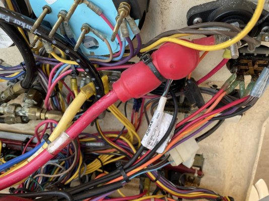
Primary helm feed picture attached.
Primary Helm Feed.jpg
 
Primary helm feed picture attached.
View attachment 138575

That primary power post at the helm looks ok, but you never know for sure until you remove and clean it as well as the other end of it down at the power panel and the battery switch under the galley.
 
Can’t tell from the photo but I like to put the main feed cable on the power post first. Then stack the biggest draw onto the post and so forth. Then put Boeshield on and then put the insulator cap on over the top to prevent possible shorts.
 
Dennis,

Would you like some pasta sauce to go with that? :flowers:

All seriousness I also think you need to clean up the wiring and install some positive and negative battery terminals. Looking at the photos I can see some rust and discolorations on the back of the gauges on the right side or the photo.

If it was my boat I would install a breaker panel with terminals to connect everything to. I believe by the time you do that the problem would disappear.
 
For those unfamiliar with the 30 Pilot II, what you are seeing in the OP's photo is the underside of the pivoting helm console at left center where the Faria cluster gauge resides. It pivots back on lower hinges almost 60 degrees, and the wiring back there needs a lot of service looping. It is a far, far different sort of installation from what I had on my Grand Banks where all was static and neatly bundled. Looking at the front of my own console, you can begin to get a taste for the density of wiring back there. Sections of it can be tied together as you see in the photo, and that is pretty much factory install - not a lot one can do to neaten it all up in the small space under there. There is no depth for everything to fall into; it all squashes up against the angled fiberglass flat underneath the console which is part of the overhead of the head directly below - like packing an overstuffed suitcase. Unshown is a an expansive ground bus bar off to the left in the photo (up in the center of the console shell). A single breaker at the power panel in the downeast cabin controls console power while a second breaker controls engine circuits. The wire bundle leads off to a hole on the stbd side and is about the side of my forearm.
 

Attachments

  • DSC03899.JPG
    DSC03899.JPG
    162.1 KB · Views: 42
Dennis
Welcome aboard TF. Always glad to see more Mainship owners join us.
I agree with suggestions so far and will add a few thoughts.
You mentioned V drop but didn't list the resting Batty V. Is the batty showing a full charge after charging/resting?

I have documented some of my MW 34HT electrical mods on my Bacchus website (signature link) - projects - Alt & Shore Charging Mods. MS used diode isolators for charging house / start / thruster banks and I was not getting a full charge underway and did have some electronics drop out issues. Since the initial mods I have since moved mt eng start from the house/start bank to my thruster bank leaving a pure house bank. Since that move I have not had any electronics drop outs.
When cleaning & checking connections don't forget the ground side... many forget that and grounds can be problematic.
Also check V drop across the batty selector sw. I have seen write-ups (steve Cyr's Stella Blue website - https://scyr.org/stellablue/index.php) where he chased an electronic problem that ended up being the result of bad connection in the main batty Sw.

Good luck and please report back with your findings for others benefit.
 
Last edited:
years ago i re-configured the battery layout on our 34 pilot. i moved thruster, genset start, yanmar start to one "start battery" and everything else to "house". at the same time switched from 1 8D to 2 6vgc. i have an acr combiner joining the banks when voltage is present. in 10 years it has worked as planned with no surprises. we anchor/mooring a lot so batteries get a lot of use. 99% of the time you're not starting an engine AND using bow thruster at the same time but if that is a worry start the genset til you upanchor/drop the mooring.
 
years ago i re-configured the battery layout on our 34 pilot. i moved thruster, genset start, yanmar start to one "start battery" and everything else to "house". at the same time switched from 1 8D to 2 6vgc. i have an acr combiner joining the banks when voltage is present. in 10 years it has worked as planned with no surprises. we anchor/mooring a lot so batteries get a lot of use. 99% of the time you're not starting an engine AND using bow thruster at the same time but if that is a worry start the genset til you upanchor/drop the mooring.

John, that's pretty much the arrangement I ended up with on my 30 Pilot II which came with only a pair of 12-V AGM start batteries paralleled as house/start - very unsatisfactory from my point of view. Ripped out the obsolete battery isolator and the electronic shifter with its flooded lead-acid battery; added two 12-V Optima AGMs in parallel as a house bank; updated battery charger with Blueseas ACR. Heavy loads connected as you have. Of note is the fact that few 30 Pilots (as the OP has) came with generators; so that may not be an option for him.
 
Since the primary terminal is powered with a battery cable and the controlling switch is located on the 12 volt panel, I assumed there was a relay or solenoid in the system. So at some point does this battery cable terminate to a 14 gauge wire to the switch?
 
Since the primary terminal is powered with a battery cable and the controlling switch is located on the 12 volt panel, I assumed there was a relay or solenoid in the system. So at some point does this battery cable terminate to a 14 gauge wire to the switch?

Great point! I am checking separately with several other 30 P II owners and will examine mine again today when I get back home.
 
After the above-promised examination of my 30 Pilot II Helm Console power supply, where the OP seems to be experiencing a voltage loss, I find that there is no solenoid or connection between power cable post in the OP's photo and the circuit breaker panel EXCEPT at one of the three power posts behind the power panel. At that post the large cable terminates, and AWG10 (or maybe larger) wire runs between it and the load side of the helm console breaker. The other side of the breaker uses that AWG10-ish size wire to connect to another power post where my house bank's battery cable connects. The stock 30 Pilot II does not come with a house bank simply using the OEM start/house bank battery for all 12-volt power on the boat.

I did find a loose screw on the load side of my Helm Console breaker, even though I was not suffering any voltage loss at the helm.

Finding the cause of any power loss at the console's power post should be a very straightforward case of checking the breaker and the connections to it from battery supply.
 
Voltage problems

I had the same problem with my VHF and plotter conking out intermittently. I decided to run a new, dedicated lead from the breaker to the VHF radios and the plotter on the bridge. It solved my problems.
 
Usually when we buy a flybridge boat I end up running a new heavy duty positive and ground cables from the batteries through a circuit breaker and up to the bridge. Usually the builder doesn’t provide adequate power to the bridge. I add a separate power panel and put all the electronics on it and leave the OEM power for the lesser draws, like lights etc.
 
This may be far out from your problem, but I will mention it anyway FWIW. I have helped quite a few people at our marina exorcise a "low voltage at the upper helm" problem that seemed to baffle them. They would measure the voltage at the battery, and then at the upper helm (with instruments turned on) and sure enough there would be a voltage difference. I have even seen one case where the 12V + wire was increased in size to an almost ridiculous size to no avail. What the owner was overlooking was that they did their upper helm voltage measurement between the negative common up there and the positive common up there. They did not remember that voltage drop can also come from resistance in the negative lead, and they were assuming the low voltage issue to be either the "hot wire" (to use their erroneous term) as too small, or a resistive connection in the +12 volt path. In fact, it turned out to be that the voltage loss was in the negative path, and this was confirmed by taking a LONG "wander-wire" lead from their voltmeter negative probe all the way back to the battery negative post and then measuring the + 12vdc voltage at the upper helm positive main junction. Lo and behold, there was pretty much the same voltage (or close to it) as measured right across the battery terminals itself. The task then was to track down the source of resistance in the negative lead. Moving the "wander-wire" lead along various points in the negative run to the upper helm found the culprit resistive junction.
 
Good thinking, I did run a second positive directly from the battery to the helm area. Using the same ground I was able to measure the voltage drop. I then concentrated on the positive side.
 
Resolution: While tracking down the wiring and looking for a solenoid that does not exist, I did find one of the large terminals near the Battery Switch that was loose. Cleaned the terminal and tightened. I installed a voltage meter directly to the primary helm terminals with the display visible at the helm. Measured 13.5 with battery charger running and 14.2 while running at cruise speed, very consistent with all gear operating.
 
Resolution: While tracking down the wiring and looking for a solenoid that does not exist, I did find one of the large terminals near the Battery Switch that was loose. Cleaned the terminal and tightened. I installed a voltage meter directly to the primary helm terminals with the display visible at the helm. Measured 13.5 with battery charger running and 14.2 while running at cruise speed, very consistent with all gear operating.

Good Job! I have a small diameter digital voltmeter at the helm with a double throw switch enabling me to read either start or house bank battery voltage.
 
Good work and good example of the KISS principle. Always check the easy stuff first.
 

Latest posts

Back
Top Bottom