questionmark
Senior Member
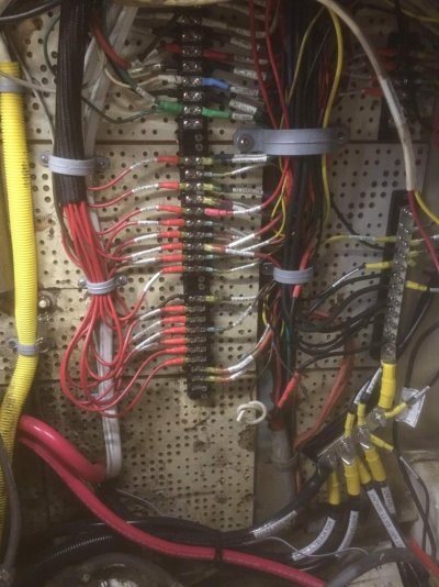
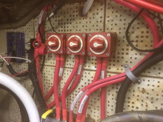
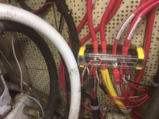
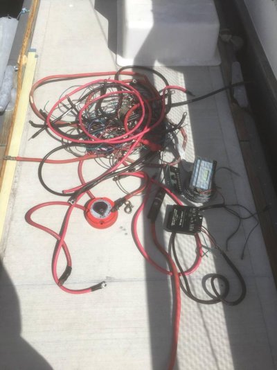
I’ve redone the house wiring and the AC system, but the battery wiring to the primary switch is original. And after wasting most of a day yesterday just trying to run it all down, I’ve decided to rip it all out and start fresh. This whole thing was precipitated by my purchase of an arch and 600w of solar panels to alleviate engine and generator run time on the hook.
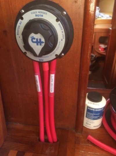
The current battery situation is 3 sets of Trojan T-105s, sort of set up in the “2 for house, 1 for start” type configuration, except there’s tons of random stuff just tapped off in random places (of course, unfused.) The two sets for “house” have a 1-2-off switch mounted between them. That runs through an unlabeled fuse through a run of unidentified wire and to another 1-2-off switch to join with the “start” bank (on position 2) which is run with what looks like welding cable (either way it’s black for positive.) I’ve just been running everything in the “all” position and pretending it’s fine because it works.
The wiring is a hodge-podge of different gauges and types. No two of the battery connects is the same, neither in gauge nor wire type nor length.
So, my current plan is this:
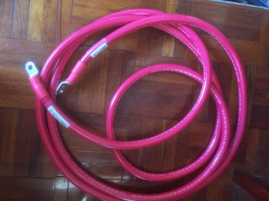
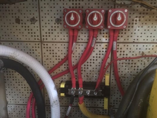
All new battery cables with proper crimps and heat shrink. Each bank will run to an “on-off” switch (through a 150 amp fuse at the battery), which will then join at a covered primary bus bar. This will give me the ability to isolate any one battery pair should there be a problem (bad cell or whatever.) Phase 2 will involve a dedicated starting battery with an echo charger, but for now I’ll just start off the one big bank.
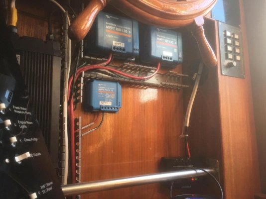
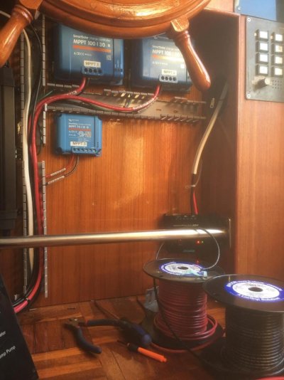
All charging will land on the primary bus bar. Alternator is new (blew up another rebuilt auto one so broke down and upgraded), and so is the 100amp charger (Magnum inverter/charger.) The arch for mounting the solar arrived today, so I’ll have 800w of solar (200w now) when I’m done. That’s 2 each of 300w panels with their own controllers, and my current 2 each 100w panels in parallel to a third controller.
All cabling will be 2/0 except the run from the inverter/charger, which will be 4/0. I have a nice hydraulic crimper for the ends and a fair amount of experience in using it. I got a smoking deal on two spools of Ancor 2/0, so even though the math works out for 1 gauge, it was cheaper to go this route. Plus I already had the terminals in 2/0 so that saved even more.
House usage has been between 85 and 100 amp hours per day. I am three reading lights away from being all LED lighting, and I’m adding a deep freezer unit which should add another 40-45 amp hours depending on ambient temperature. I’m estimating 150 amp hours per day draw for planning.
The current plan is to cruise down to the Sea of Cortez this winter. We’ll need to be back in a marina every couple of weeks because my son’s school will require him to check in via video-conference regularly. So figure two to three week cruises at a time. The longest we’ve done so far was two weeks, and that’s why we ordered the freezer...
Any advice, or anything I’ve missed? I’ll try and take pictures, but sometimes I get on a roll and forget.
Josh
Last edited:



 You're welcome. Hope it helps.