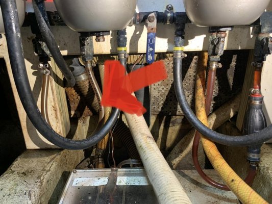
I can't really tell what is going on from the pictures.
I'd start by creating a drawing showing the fuel path from the tanks to the engine lifter pumps including all if the valves/manifolds, filters, drain, connections, etc, in between.
Then I'd do the same from the engine return rail back to the tanks, or, if you prefer, from the tanks to the engine return lines.
It is too hard to understand the system confidentially without that or without enough pictures to create that.
If the engines are running fine and you have two /pairs/ of filters, I'd guess that the engines are getting fuel. So, I'd further guess that the air in the line is in a path that isn't presently being used for fuel supply or fuel return. So, I'd further guess that it is associated with the supply or return to a filter that has been removed from the supply loop by the present valve/manifold configuration and that the air is also trapped or unmotivated to.move by the closed valve(s) or associated restriction in fuel flow.
Getting the air out probably means setting the correct valve configuration for that purpose and then bleeding the air, bleeding as much as possible near then filter or tank and the rest at the engine, as needed.


