Yanmar water pump impeller project

The friendliest place on the web for anyone who enjoys boating.
If you have answers, please help by responding to the unanswered posts.

garmstro55

Senior Member
Joined
Mar 25, 2018
Messages
405
Location
USA
Vessel Name
Seventh Sojourn
Vessel Make
Mainship 400
I am feeling kinda stupid as I have not yet figured out how to change the water pump impellers on my 4LHA-STP 240 HP engines. I get down into the engine room every once in a while and stare at the engine but I can't figure out where to start. Maybe one of my TF Mainship buddies can tell me how to get going. (Doug?, RichG? Bueller?)

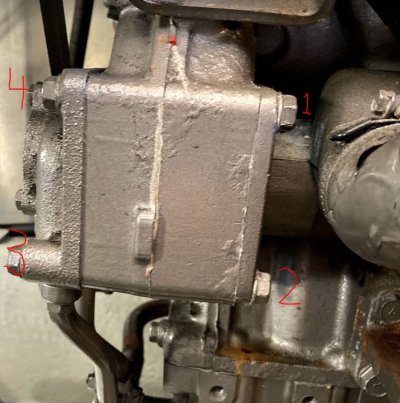
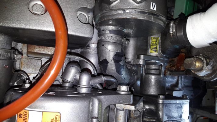
First picture: I think this is the pump. Do I remove bolts #1 and 2 and the other two you can't see on the backside? Or do I remove the bolts #3 and 4 and the two other on the front side?

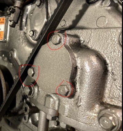
Or is the impeller behind the triangular shaped cap with the three bolts.

Or none of the above?

TIA

Gary
 

Attachments

  • Pump1.JPG
    Pump1.JPG
    98.4 KB · Views: 122
  • Pump2.JPG
    Pump2.JPG
    140.4 KB · Views: 137
Gary,

Not sure if you have the engine operating manual, but first link below will let you download it. It shows the sea water pump, but is very misleading in the image where you inspect the impeller in place. There is no room on the backside to open up the pump. I have found it necessary to remove the pump and at that point, I'm replacing the impeller instead of just inspecting it. In removing the pump, I've also found it easier to remove the alternator and bracket to gain extra room.

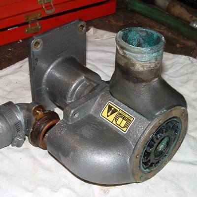
The second link is a replacement pump for sale on Ebay that has some good pictures of what you're dealing with. To remove the pump, shut off the sea water intake, and remove the inlet and outlet hoses. If I recall correctly, your numbers 1 and 2 are thru bolts and 3,4 are the nuts. You need to remove both bolts as well as the 2 hidden ones that screw into the engine block. You can then remove the pump, inspect, replace impeller and gasket, and reassemble the pump. I seem to remember there being some difficulty engaging the splined shaft and aligning the bolt holes, but patience will serve you well. This is all easier on the starboard engine where you have room between the engines to work, rather than port side where you're on the outside of the engine.

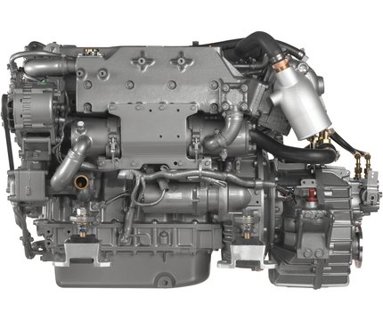
The picture is from the Yanmar site and you can see the pump inlet and the hose from the outlet to the heat exchanger. This should help get you oriented. Lastly, the triangular cover in your other picture is, I think, the oil pump.

I hope I've been able to shed some rather feeble light on the topic. I'm sure others will chime in with more details.

Brett


https://www.yanmarmarine.com/Products/Powerboat-Engines/4LHA-STP-341/

https://www.ebay.com/p/9030049595?i...MIhanMovno6QIVWMDICh2e9gjUEAQYBCABEgIXx_D_BwE
 

Attachments

  • 4LHAphotogallery03.jpg
    4LHAphotogallery03.jpg
    107.1 KB · Views: 155
Looking at the manual Bacchus posted (thanks Don), page 252, section 6-4, it appears I misremembered some details . Bolts 1,2 are not thru bolts and the back two are studs with nuts. It is these studs that make it tricky to align the spline, since the studs require the pump in a certain orientation and the splines require the shaft in a certain orias well. I seem to remember a post where someone replaced the studs with bolt to allow the splines to be inserted then the pump body can be turn to allow the bolts to be inserted. Alternatively, one could mark the shaft upon disassembly and ensure it is in the same orientation.

Brett


This.


The hardest stud to get to is the one in the 1:00 position, a ratcheting box end wrench helps a lot, well worth the investment. You can carefully hold the bolt in the wrench, slip it into place and get your finger on the bolt to start it threading. Hard to describe but you will see what I mean. Once the bolt is threaded it's just a whole bunch of tiny wrench spins to tighten it up. Take the outlet hose off the pump before you pull it but leave the inlet hose on until after the pump is pulled. Getting the pump off/on gets easier as you do it more often.


Marking the spline is a good idea, which I have not tried yet, but plan to at my next impeller change.


You can PM me if you have questions.


Doug
 
I might try this weekend. I think part of my problem is that I can't see anything with the hose still connected.

Also gonna install the 4-function gauge Brett sold me and also putting in the Balmar SG200.
 
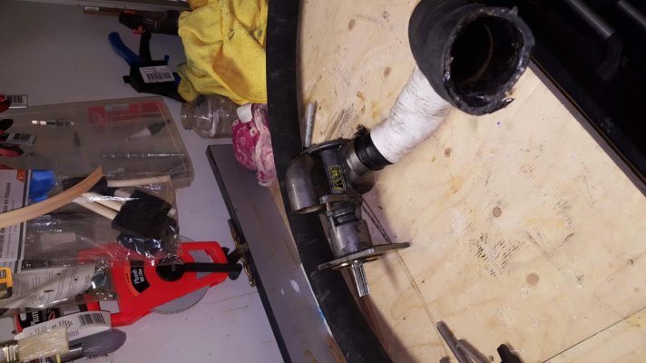
This ours on the bench
 

Attachments

  • Water Pump (2).jpg
    Water Pump (2).jpg
    124.2 KB · Views: 120
  • Water Pump 6LYA.jpg
    Water Pump 6LYA.jpg
    147.7 KB · Views: 94
  • Water Pump on the bench.jpg
    Water Pump on the bench.jpg
    95.3 KB · Views: 102
That is the fresh water side. Do not touch. Follow the hose from seacock to the engine. You will see that hose and another from that point into the engine. Behind that pump you will see a round plate with about 5 small screws. The impellor is in there. The port engine will have to be done by feel or you can remove the entire water pump. I can do it by feel. Have the yard do it, if you are unsure.
 
Back
Top Bottom