Mainship 34 Pilot Electrical Questions

The friendliest place on the web for anyone who enjoys boating.
If you have answers, please help by responding to the unanswered posts.

LakeErieWX

Member
Joined
Aug 23, 2022
Messages
20
Late last year we purchased a 2001 Mainship 34 Pilot. One of my projects for this winter is to make sense of the DC electrical system. I have a basic working knowledge of electrical systems, but this experience is based on owning older sailboats with much simpler systems (and no inverters). I am a bit confused by the arrangement I have inherited.

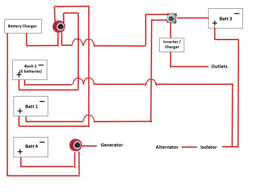
My current questions relate to charging and the connection between the batteries and the inverter charger. I have attached a simplistic diagram for reference.

There are 6 group 27 batteries on board and all are starting batteries. Three of the batteries are individual (#1, #3, and 4). Bank 2 contains three batteries in parallel.

Question 1: Battery 1 is connected to position 1 of the primary battery switch and the switch associated with the inverter. So even when the primary battery switch is off or set to position 2, battery 1 is connected to the inverter/charger. Is this standard?

Question 2: Battery 3 is connected directly to the inverter switch. It is charged via the alternator and the inverter/charger when the inverter is on A/C power. Based on my understanding of the wiring diagram, battery 3 would also be charged by the battery charger if the primary battery switch was in position 1 or All and the inverter switch was on. Is this correct?

Question 3: Based on the configuration, it seems that Bank 2 is the starting bank and battery 1 and 3 are for house loads. Does this seem correct?

Question 4: If battery 1 and 3 are for house loads, shouldn't they be deep cycle instead of starting batteries?

Question 5: Would it be simpler to combine battery 1 and 3 into a bank, connect the bank to position 1 of the primary battery switch, and remove the direct connection from battery 1 to the inverter switch?

Question 6: Would it be simpler to replace the 2 bank charger with a 3 bank unit and running the charging feature on the inverter?

Question 7: Would it be a better arrangement to replacing the battery isolator with an ACR?


Thanks!
Mark
 

Attachments

  • Osprey_Wiring_Diagram.jpg
    Osprey_Wiring_Diagram.jpg
    69.5 KB · Views: 33
Wow, that’s an unusual arrangement. Seems like lots of opportunity for user error.
Looks like battery 4 is only for generator starting, that’s good. For the rest, I think I’d go with 2 batteries for the start bank, use the 3 battery group for house and inverter loads. (Change to deep cycle)
Get rid of the isolator. Use acrs instead. I’d route the alternator output to the house bank, and let the acrs bring the others online.
Simplify, and make it automatic. Use the inverter/charger for charging all batteries when on shore power or generator, save the other charger for backup.

This is just a first look opinion. There may be better ideas with a little more thought.
 
On Questions 1. If I am reading this right. You want to be able to kill the power to the inverter if needed. So, in the off position, no power to the inverter. Lets say you had to change it out. Would you want the DC power on?

On Q 2. It sound like you have shore power on and the engine running. Yes? I would say you are correct BUT why would you have condition? At the slip, shore power on and off the docks engine running. Not sure of switch positions and which lugs the cables are on. I would need a better diagram.

On Q 3. Personally, I would go from 4 to 3 banks. House being the largest and charged off the ALT and the charger/inverter. Than stating and genset bank using ARCs. Now it questionable that a ARC is needed on the genset since it has its own ALT. I used one that I can disable for boating season and enable it for the winter. In the winter and spring my charger/inverter can charge all 3 banks. Buts thats me...

On Q 4. Yes, deep cycle in the norm. But I/we don't know the size of the batteries and your needs. So you could be fine.

On Q 5. See "On Q 3"

On Q 6.Use the 2nd charger as a bank up. No need for a 2 or 3 bank charger. You have the charger/inverter.

I like using ARCs, buts thats me. Keep in mind, that some of the older isolators have a .6 voltage drop. The newer ones don't. So you may not want to change it out.


Must take my dogs out now. More later!
 
Last edited:
Bmarler,

Thanks! It's great to hear that I'm on the right track.

Mark
 
Last edited:
Iggy,

Thanks for the reply.

On question 1, I can disconnect the inverter from power by using the switch. I was curious why battery 1 was wired to the primary battery switch and the inverter input. It seems redundant since power flows from the battery switch to the inverter input.

On question 2, I wasn't considering running the engine while the shore power circuit was active.

Mark

Yes, you can disconnect D.C. power from the switch. Provided you have no inverter loads.
 
Based on the replies here and additional research online, I am working on a revised layout that consolidates batteries into banks, eliminates confusion and the need to constantly change the battery switch between house and engine.To keep things simple, I have excluded fuses, etc. from the diagram.


Am I on the right track?


Thanks,
Mark
 

Attachments

  • Osprey_Wiring_Diagram-Proposed.jpg
    Osprey_Wiring_Diagram-Proposed.jpg
    65.7 KB · Views: 16
Based on the replies here and additional research online, I am working on a revised layout that consolidates batteries into banks, eliminates confusion and the need to constantly change the battery switch between house and engine.To keep things simple, I have excluded fuses, etc. from the diagram.


Am I on the right track?


Thanks,
Mark

Looks good, with one exception. I like to aim the alternator at the house bank first, then let the combiners come on to bring up the others. The house bank is the one that needs the most power input.
Another way people do it is to use dc to dc chargers. They are better at controlling the charge into the other batteries than combiners are.


Thanks! I was considering which bank was preferred for the alternator.


Mark
 
Looks good, with one exception. I like to aim the alternator at the house bank first, then let the combiners come on to bring up the others. The house bank is the one that needs the most power input.
Another way people do it is to use dc to dc chargers. They are better at controlling the charge into the other batteries than combiners are.

What he said....

Generally that ALT charges the largest bank which in most cases is the house.

With DC to DC chargers you can control the output of the ALT. In other words, the load that the ALT sees. What ever the charger is rated for. With that in mind, a heat sensor on the ALT can help drop the output if it gets too high.
 
I "think" you are on the right track. Any chance you could mark on the drawing what each switch is? On/Off, Off-1-2, Off-1-2-both? And where applicable, which is the common terminal? From teh drawing I can't tell where you have two wires stacked on the same terminal, nor which wires get switched in what ways. The switch with only two wires is obviously an On/Off, but I don't want to guess about the others.
 
Looks good, with one exception. I like to aim the alternator at the house bank first, then let the combiners come on to bring up the others. The house bank is the one that needs the most power input.
Another way people do it is to use dc to dc chargers. They are better at controlling the charge into the other batteries than combiners are.

I would say there are 2 schools of thought here...
Alt feeding house is one with the benefit you cite. The downside is the start bank charge will be delayed by some amount while the house bank comes up.

Alt feeding start bank has some advantages IMO... simple starting doesn't remove too much and the start bank will come up to full power fairly quickly and then charging will be to the house. You will have full starting power should you need it. In addition, if you ever decide to go LiFePO on the house there will be fewer changes req'd to switch Alt charging as my understanding is Alt charging a LiFePO bank w/o Alt protection can be acserious issue.

I total get where your coming from! For the benefit of the op. :thumb:

The way look at it, but thats me... When leaving my slip all the batteries I would hope are fully charged. (On a mooring over night, battery levels could be different.) So the starting load on the starting battery/s should not be much at all for one start. The house bank should be fully or close to it being charged.

Planning to LifePO is not a bad thought ether. But not a big deal. You just need to move two wires. The sense wire the the ALT wire to the starting bank.
 
Last edited:
I understand the school of though on recharging the start batteries first. My thinking on that is similar to iggys. The start bank should be sized to handle a few starts without depleting it substantially.
If you aim at the house bank first, you can reduce the amount of time the start bank is bulk/absorb voltage, especially if the combiner has adjustable set points.
 
@Bacchus #12
Starting even very large (1000hp) engines takes a couple of Ahr at most.

I have two recommendations:
1. Charge the large house bank with all charging sources and then "spill over" the few Ahr required to top up the starting battery with any of many different devices.
2. Replace every 1-2-All battery switch with simple ON-OFF switches. This eliminates any confusion about what effect a switch position will have on the system.

I have used this schema on literally dozens of installations with excellent results.

NOTE: I have asked every boat owner that has engaged me to sort out DC problems the following: "Which battery is Battery 1 and which battery is Battery 2?" on a 1-2-All switch.
In 23 years, I have had one owner answer correctly! All others reply; "They" told me to leave the switch on All. I have replaced a lot of 1-2-All switches with Blue Sea Systems m/n 6006!!
 
I understand the school of though on recharging the start batteries first. My thinking on that is similar to iggys. The start bank should be sized to handle a few starts without depleting it substantially.
If you aim at the house bank first, you can reduce the amount of time the start bank is bulk/absorb voltage, especially if the combiner has adjustable set points.

Unless he has a programmable V regulator the Alt doesn't switch from bulk/absorb , or float so that doesn't seem to matter. It's not a big deal and not trying to defend my comment or suggestion as either will work.
To be honest my set up is Alt runs through a Sterling CVSR and my house is primary. That was installed prior to my moving my single eng start to my thruster bank leaving a pure house bank rather than the start / house arrangement MS installed.

For shore charger.... most don't allow different profiles so whatever is selected / programmed will simply be split to multi banks.

Yes, either will work. Especially with “dumb” charging sources. The battery life may or may not be affected by which is first in line. All will be charged in the end. Using programmable devices just adds better performance, and better battery life (hopefully).
 
Just took a quick look at the sterling cvsr. Looks like a very solution for a battery combiner. I wasn’t waste of its existence till now. There are very distinct advantages to using it over standard vsr’s. Op might want to consider it.
 
Just took a quick look at the sterling cvsr. Looks like a very solution for a battery combiner. I wasn’t waste of its existence till now. There are very distinct advantages to using it over standard vsr’s. Op might want to consider it.

It is a significantly different combiner than many.
More details & links available on my Bacchus website - Projects - Charging System Mods
My concern when planning for my changes I was concerned that if my thruster and (then) house/start bank were combined and I operated the thrusters would the combiner handle a possible hi amp "back flow" from house bank to thruster load?
Some of the mfg indicated their units would not be recommended for that application. Sterling said no problem... their unit was designed to handle hi amp loads via a controlled disconnect. It has worked perfectly for me for almost 10 yrs. I have since moved my single eng start to the thruster bank to leave a pure house bank with normal house loads.
 
Thanks for the replies, I appreciate the advice.


Attached is an updated schematic. The battery switches will be On/Off only so there will be connection between the banks during discharge.


I have a couple of questions about the revised layout:


  • The engine bank is currently the largest and will handle engine starting, the windlass, and thrusters (bow and stern). In this situation, is directing the alternator to the house bank (bank 1) still recommended?
  • If the alternator is directed to the house bank, the DC to DC charger is used to charge the engine bank (bank 2). Should the battery combiner that charges Bank 3 be connected to the house bank (bank 1) or the engine bank (bank 2)
It is not on the layout, but I am considering adding a e-Series Dual Circuit Battery switch to connect Bank 1 and Bank 2 in the event that the engine bank was inadequate to start the engine. Any thoughts on this device?


Thanks,
Mark
 

Attachments

  • Osprey_Wiring_Diagram-Proposed-11.13.2023.jpg
    Osprey_Wiring_Diagram-Proposed-11.13.2023.jpg
    71.3 KB · Views: 15
Thanks for the replies, I appreciate the advice.


Attached is an updated schematic. The battery switches will be On/Off only so there will be connection between the banks during discharge.


I have a couple of questions about the revised layout:


  • The engine bank is currently the largest and will handle engine starting, the windlass, and thrusters (bow and stern). In this situation, is directing the alternator to the house bank (bank 1) still recommended?
  • If the alternator is directed to the house bank, the DC to DC charger is used to charge the engine bank (bank 2). Should the battery combiner that charges Bank 3 be connected to the house bank (bank 1) or the engine bank (bank 2)
It is not on the layout, but I am considering adding a e-Series Dual Circuit Battery switch to connect Bank 1 and Bank 2 in the event that the engine bank was inadequate to start the engine. Any thoughts on this device?


Thanks,
Mark

As mentioned, you generally charge the biggest bank off the Alt. Your not showing how the charger/inverter is going to handel the batteries.

I would use a simple on/off switch to combine the banks if needed for starting.
 
Mark
I'm not sure I understand your diagram where you show a third or fourth connection to an on/off switch... are they multi inputs or outputs?
Also it seems to me that using all simple on/off switches complucat3s it when wanting to retain flexibility to combine multi banks to an output... e.g. starting it seems thatbav1-2-all switch could replace 2 on/off why add complexity?
I havevadded labels to my switches to clarify what 1&:2;represent... I can combine house & gen battys to either charge Mt gen batty or use house to supplement a weak (separate) gen batty to provide emergency charging when battys arenlow.
 
As mentioned, you generally charge the biggest bank off the Alt. Your not showing how the charger/inverter is going to handel the batteries.

I would use a simple on/off switch to combine the banks if needed for starting.


Iggy,

Perhaps my drawing is creating confusion, but the charge from the inverter would be connected to Bank 1. As with the flow from the alternator, the charge from the inverter to Bank 2 from the DC to DC charger and Bank 3 through Combiner 1. Does this make sense?

Thanks,
Mark
 
Last edited:
Mark
I'm not sure I understand your diagram where you show a third or fourth connection to an on/off switch... are they multi inputs or outputs?
Also it seems to me that using all simple on/off switches complucat3s it when wanting to retain flexibility to combine multi banks to an output... e.g. starting it seems thatbav1-2-all switch could replace 2 on/off why add complexity?
I havevadded labels to my switches to clarify what 1&:2;represent... I can combine house & gen battys to either charge Mt gen batty or use house to supplement a weak (separate) gen batty to provide emergency charging when battys arenlow.


Don,

I think the only battery switch with multiple inputs is the one for Bank 3. The inputs are the battery, the backup battery charger, and the flow via combiner 1.

The battery switches are inconveniently located in the engine compartment under the bridge deck. It's a hassle to clear the bridge deck, raise the floor, and set the switch from house to starting. My goal (which may be misguided) is to to isolate house loads from the starting bank without the need to enter the engine compartment.


Thanks,

Mark
 
Seems like it would work. Maybe do like you thought though, and use the combiner(vsr) from bank 2 to bank3. That would eliminate the backup charger output to bank 3 as it always charges from bank 2.
I’d still aim the alternator at the house bank as it will likely be at the lowest state of charge.
Don’t have any experience with the other combiner your mentioning, but a remote activated combiner might be a good idea if it’s a pain to get to the switches. Really though, I’d try to figure out a way to access the switches easier.
If the start battery is flat for some reason, you can always fire up the genset and use inverter and backup charger to juice things back up.
So many ways to do a thing, right?
 
Back
Top Bottom