replace a gfci outlet

The friendliest place on the web for anyone who enjoys boating.
If you have answers, please help by responding to the unanswered posts.

paulga

Guru
Joined
May 28, 2018
Messages
1,023
Location
United States
Vessel Name
DD
Vessel Make
Marine Trader Sundeck 40'
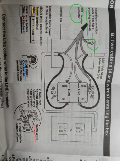
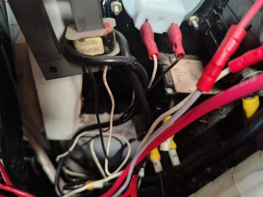
a gfci outlet in the ER stopped working. it would trip immediately as a heater is plugged in. The heater works fine using other gcfi outlets. so I bought a new gfci outlet, but the manual is not adequate for me to replace it.

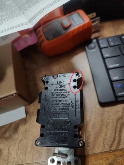
I saw each terminal has two wire holes. why do they provide two holes for each terminal?

Image_20240128231938.jpg

does the electrical box on a boat usually has a grounding terminal? if not, should both the LINE and LOAD cable's green wires be connected directly to the ground terminal on the gfci?

what is "back wire"? "screw terminal wire"? "side wire"?

Image_20240128231949.jpg
 
a gfci outlet in the ER stopped working. it would trip immediately as a heater is plugged in. The heater works fine using other gcfi outlets. so I bought a new gfci outlet, but the manual is not adequate for me to replace it.

I saw each terminal has two wire holes. why do they provide two holes for each terminal?

View attachment 145387

does the electrical box on a boat usually has a grounding terminal? if not, should both the LINE and LOAD cable's green wires be connected directly to the ground terminal on the gfci?

what is "back wire"? "screw terminal wire"? "side wire"?

View attachment 145388

This refer to the way you wire the outlet. You can either use push in wire connectors (the holes) or screw connectors (on the side).

These are "house" outlet used with solid wires that can be pushed into the holes.

On boat solid wires are prohibited based on ABYC standards so side screw connectors should be used with stranded wires and proper crimped connectors.


L
 
Backwiring requires solid core wire, which we don't have in boats. Basically, you strip the end of the wire the correct amount and then push the stripped end of the wire into one of those holes and an internal clamp sort of ratches onto it and holds it in place. It doesn't work with the stranded wire we have on boats. And, even in the applications for which it is designed and approved, most serious electricians and contractors will pinch their noses and turn away if it is mentioned. It is, in practice, a pretty poor way to make a connection. So, you most definitely don't want to backwire the outlet.

Some of these don't have internal clamps and, instead, the side-wire screw is screwed down to tighten up the back-wired wire. This still isn't as good as side-wiring, because the wire clamps a straight wire, rather than a loop of wire (see below)

In a non-boating application, side-wiring means striping the end of the wire the correct amount, twisting the stripped end around needle nose pliers in the direction screws tighten (clockwise), looping it over and then pulling it under the side screw terminal, and tightening down the screw to make a solid connection. It works very well with solid wire.

The unfortunate problem about almost every, if not every, GFCI outlet I've ever seen is that it isn't designed for marine stranded wire. Wrapping stranded wire under the screw terminal will result in it flattening out and making a poor connection, rather than being clamped as a solid wire does.

So, what to do? We can't use the back wiring, because it is for solid wire, and a bad idea, anyway, and we can't use the screw down terminal, because it doesn't work well with stranded wire, either?

There are a few things I've heard of people doing. Below are a few of them. I don't know if there is a best answer, or if there is, what it is:

1) One can crimp small ring connectors onto the end of the wire, back out the terminal screw entirely, place the screw through the connector, and then screw it back down. This isn't as easy or as correct as it might initially seem. The screws are designed not to be fully removed. The initial bit of thread is intentionally damaged to prevent them from easily coming out. They can be backed out, but they do might do a little damage to the threads within the outlet on the way, and getting them started again going back in can be a little trickier than normal.

And, there is another challenge. There is a often a little raised bit of plastic in front of the screw that is designed to help a loop of wire sit right. It usually forces the ring terminal to sit wrong. Some tolerate this. Some use a pair of needle nose pliers to break out this nub of plastic or cut it out with a sharp utility knife.

This is a "pick your poison approach" in two ways: (1) removing and reinstalling the screws in an unauthorized modification of the device, and removing the plastic bit, if one chooses to do that, is also.

2) Some people don't want to remove the screws since, well, they aren't intended to come out. These folks often use fork terminal as one might use in other situations where one wants to use a ring terminal, but can't remove the screw. This works, but it doesn't allow for as resilient a connection as a ring terminal. And, remember that numb of plastic? Unless it is removed, it'll disturb the way the fork sits, maybe causing it to open wider, and become even less resilient. So, again, you've got to pick your poison a bit about your willingness to modify the outlet device in an unauthorized way or not.

3) Some people, for reasons I don't fully understand, take ring connectors and cut a narrow bit, sometimes V-shaped, out of the front of them to make them sort of like fork connectors. They claim that these fit better than a fork connector because the opening is smaller and the shape is round, not straight. Dunno. Insert the same discussion from about about modifying things and the plastic nub .

4) Some people do other things, such as tightly twist the stranded wire to make it more like solid wire and then use it. This doesn't work. It is still stranded wire. Some people do this, then bend it into the loop, and then solder the loop to make it solid, and then install it. This seems to work w.r.t. the screw terminal, but it leaves a weak point where the soldered wire ends and it becomes stranded again. The thin strands like to break there from vibration, etc. I won't criticize these approaches. But, I wouldn't think of either.

Blue Sea Systems, Marinco, and Hubbell all sell what I've seen advertised as marine-rated GFCI outlets. But, they've all been configured in this respect just like the land units.

As for the wiring, the AC (not DC) black wire should go to the screw behind the smaller slot. The AC white wire should go to the screw behind the larger of the slots. And the AC green wire should go to the grounding conductor screw, which is usually a green screw attached to the metal frame.

This is all assuming the boat is wired conventionally. You've got to test and verify that yourself with a meter, etc. Check to make sure hot is hot, neutral is neutral, the grounding conductor is the grounding conductor, etc. Also, work with the breaker off and verify that there is nothing hot near what you are working on, perhaps with a glowing indicator device. Assume nothing.

All of this is just conversation is about a hypothetical install that is ephemeral in my mind. It isn't about your boat. If you work on your boat, you've got to safely get it right given whatever conditions you have, safely rectifying whatever deficiencies may exist to enable you to do that. Etc. Etc. Etc.
 
Last edited:
From your electrical panel you should have a black wire (hot), a white wire (neutral) and a green wire (ground). Those should connect to the line terminals and the green ground terminal.

"Load" terminals would only be used if this GFCI is the first outlet and there are other std outlets that are "downstream". One gfci can protect the other outlets. If you only have the one outlet and you didn't disconnect any other wires from the faulty outlet then you don't need to connect anything to the load terminals.
 
READY makes a good point.

There is usually one pair of hot+neutral terminals on a GFCI labelled LINE. This is what gets connected to the upstream electricity.

There is normally another pair of terminals, labelled LOAD, often taped over with a label. This is used to "daisy chain" normal outlets from the GFCI outlet to give them GFCI protection. If this is done, and they fault, you'll have to reset it at the GFCI outlet.

Also check the breaker. Unless your GFCI's larger slot is shaped like a "T" vs a straight line, it is a 15A outlet. The upstream breaker protecting the GFCI then needs to be 15A or less. The ones with "T" shaped long neutral slots are rated to 20A.

And,of course, all of the wire used needs to be the correct gauge for the amperage distance, temperature, etc.
 
IIRC the answer to why there are two holes at each terminal location is one hole will grab a solid wire and another solid wire inserted into the other hole will release the first wire but can also be pulled out.
 
IIRC the answer to why there are two holes at each terminal location is one hole will grab a solid wire and another solid wire inserted into the other hole will release the first wire but can also be pulled out.

In my observation, this depends upon the outlet, as below. YMMV:

1) If the outlet has "push clamp" connectors, one of the two holes will be round. The other will be more rectangular. The round hole is for the wire. The rectangular one is a button that can be pressed with the tip of a small screwdriver to release the wire (with the power off, and verified to be off, everywhere nearby of course)

2) If the outlet allows for back-wiring, but does so with a screw down clamp the side-wire screw is used to either clamp down externally for side-wiring, or internally for back wiring. If this is the case, both holes are round. Neither is a release. A release is accomplished by loosening the side-screw. Instead, either or both holes can be used for wire.

Again, there may be more systems here than I've seen or than I remember seeing.

Careful with sparky!
 
IIRC the answer to why there are two holes at each terminal location is one hole will grab a solid wire and another solid wire inserted into the other hole will release the first wire but can also be pulled out.

Thanks. that's interesting design.
 
There is a huge difference in "house" wiring and ABYC wiring standards. Please contact a licensed electrician. Heaters are high amperage draws in the winter time.
These are not DIY projects.
 
READY makes a good point.

There is usually one pair of hot+neutral terminals on a GFCI labelled LINE. This is what gets connected to the upstream electricity.

There is normally another pair of terminals, labelled LOAD, often taped over with a label. This is used to "daisy chain" normal outlets from the GFCI outlet to give them GFCI protection. If this is done, and they fault, you'll have to reset it at the GFCI outlet.

Also check the breaker. Unless your GFCI's larger slot is shaped like a "T" vs a straight line, it is a 15A outlet. The upstream breaker protecting the GFCI then needs to be 15A or less. The ones with "T" shaped long neutral slots are rated to 20A.

And,of course, all of the wire used needs to be the correct gauge for the amperage distance, temperature, etc.


Thanks for all the details

"The upstream breaker protecting a 15A GFCI then needs to be 15A or less" - does "upstream breaker" refer to the breaker in the AC service panel?

the gfci outlet that I purchased is 20A, its longer slot is a T shape. I remember it may not be installed to a 15A circuit. but boat circuit is 30A? so a 20A gfci can be used?
 
a gfci outlet in the ER stopped working. it would trip immediately as a heater is plugged in. The heater works fine using other gcfi outlets. so I bought a new gfci outlet, but the manual is not adequate for me to replace it.

I saw each terminal has two wire holes. why do they provide two holes for each terminal?

View attachment 145387

does the electrical box on a boat usually has a grounding terminal? if not, should both the LINE and LOAD cable's green wires be connected directly to the ground terminal on the gfci?

what is "back wire"? "screw terminal wire"? "side wire"?

View attachment 145388

PLEASE! Back away and put the wire cutters down. Get some competent help with this replacement. If you don't know what you are doing, you could make a mistake that could be lethal at some point.

There is no shame in hiring a pro to do what you don't know how to do and you aren't going to get this right by asking on a boating forum.
 
Greetings,
Ms. p. No idea what they're called. IF you are going to be doing ANY electrical work, KNOW what you're doing! Substandard wiring, equipment (non-marine) and connections in either 12v or 110/220v can easily start a fire and burn your boat to the waterline.


As for crimpers and connections, I would suggest a good pair of ratchet style crimpers...eg: https://www.amazon.com/Klein-Tools-...&hvlocphy=&hvtargid=pla-4584276309275591&th=1
 
Last edited:
Greetings,
Mr. rw. Thanks. I didn't know that. Strike my post #8. It's a good day. I learnt something.
 
PLEASE! Back away and put the wire cutters down. Get some competent help with this replacement. If you don't know what you are doing, you could make a mistake that could be lethal at some point.

There is no shame in hiring a pro to do what you don't know how to do and you aren't going to get this right by asking on a boating forum.

Thanks for the warning.
I will seek professional attention if I don't feel comfortable doing this.
 
Greetings,
Mr. STB. Re: your post #8. These may be an option as well...


iu

PLEASE! Back away and put the wire cutters down. Get some competent help with this replacement. If you don't know what you are doing, you could make a mistake that could be lethal at some point.

There is no shame in hiring a pro to do what you don't know how to do and you aren't going to get this right by asking on a boating forum.

Can you provide more detail as to why it is not compliant. The ones you linked of course will remain in place easier until secured. But if the 'C' type is installed with the screw turn it too will remain in place until secured.
 
Use the connector that matches the size of the wire you are crimping it onto.

On my boat, for small wires I would use connectors that include heat-shrink plastic with hot glue inside to cover the crimp area. If those aren't available, or on battery-size cables, I would cover the crimp area and some of the wire with a separate piece of heat-shrink plastic tubing with hot glue inside. An inexpensive craft-oriented heat gun can do the job.
 
While I agree with the statement to seek professional help if you are unsure of what you are doing, changing out a GFCI protected receptacle is usually not difficult.

To answer your Post #1 questions:

The second set of holes on the back side (which are not used on a boat) are used with solid wire to extend the circuit further to other ordinary receptacles that will also be protected by the GFCI receptacle. In effect, if the GFCI is in the first receptacle, all other receptacles on that circuit are also protected. If the GFCI receptacle is the only or last one in the circuit, only it is protected.

Always electrically connect the green (grounding) wires from the line and load to the grounding screw on the GFCI. In addition, if the electrical box in the wall is metallic you need to connect it to the this grounding screw just like the instructions show, but do not use any wire nuts ever. One way to do this is to mount the line and load's green wire along with a short piece of green wire to the metallic box's grounding screw. The other end of this short green wire goes to the GFCI's ground screw.

Although the folded fork connector (referred to upthread) may well be ABCY acceptable, my understanding is that a locking fork connector is also acceptable. In my experience the folded forks are not quite long enough as to not be in conflict with the oversized headed screws (normally used to clamp bare wire) that are used in the receptacle's side terminals.
In addition, the folded fork connectors make it impossible to get 2 connectors on one terminal should you have an extended circuit.

Buy only good quality terminals, something like these.

https://www.hubbell.com/burndy/en/P...cking-Fork-Terminal-For-12---10-AWG/p/2024163

Strictly speaking it may be that the use of a 20 Amp rated GFCI receptacle (where one blade of the plug is spun 90º) on a 15 Amp breaker protected circuit is prohibited, the peril here is almost unmeasurable. If you did manage to find some appliance that has a 20 Amp plug attached and powered it with a 15 Amp circuit, provided that everything is in good shape, the breaker trips.
That being said, I recommend that if you are to use this 20 Amp rated GFCI ensure that the panel mounted breaker and all of the wiring in the circuit is also rated for 20 Amps.

Please don't take this the wrong way, but your questions in Post #12 reveal that you should really learn a lot more about the electrical distribution system in your boat before you undertake any further work.
 
Greetings,
Mr. RC. I seldom use connectors with the shrink insulation. I've feel that liquid electrical tape (LET) works better. Seems there's always a void of some sort at the connection end where you can see bare wires with the heat shrink. The one caveat is that the LET is messy and takes quite a while to set up.
 
the ac breaker panel does not have amp specified under each button. here is what the back of panel looks like. it says

AMP 20
TRIP 25
VOLT 250
HZ 50/60
TD 3

does this mean the ac circuit is rated for 20 amp?

Image_20240129123341.jpg

While I agree with the statement to seek professional help if you are unsure of what you are doing, changing out a GFCI protected receptacle is usually not difficult.

To answer your Post #1 questions:

The second set of holes on the back side (which are not used on a boat) are used with solid wire to extend the circuit further to other ordinary receptacles that will also be protected by the GFCI receptacle. In effect, if the GFCI is in the first receptacle, all other receptacles on that circuit are also protected. If the GFCI receptacle is the only or last one in the circuit, only it is protected.

Always electrically connect the green (grounding) wires from the line and load to the grounding screw on the GFCI. In addition, if the electrical box in the wall is metallic you need to connect it to the this grounding screw just like the instructions show, but do not use any wire nuts ever. One way to do this is to mount the line and load's green wire along with a short piece of green wire to the metallic box's grounding screw. The other end of this short green wire goes to the GFCI's ground screw.

Although the folded fork connector (referred to upthread) may well be ABCY acceptable, my understanding is that a locking fork connector is also acceptable. In my experience the folded forks are not quite long enough as to not be in conflict with the oversized headed screws (normally used to clamp bare wire) that are used in the receptacle's side terminals.
In addition, the folded fork connectors make it impossible to get 2 connectors on one terminal should you have an extended circuit.

Buy only good quality terminals, something like these.

https://www.hubbell.com/burndy/en/P...cking-Fork-Terminal-For-12---10-AWG/p/2024163

Strictly speaking it may be that the use of a 20 Amp rated GFCI receptacle (where one blade of the plug is spun 90º) on a 15 Amp breaker protected circuit is prohibited, the peril here is almost unmeasurable. If you did manage to find some appliance that has a 20 Amp plug attached and powered it with a 15 Amp circuit, provided that everything is in good shape, the breaker trips.
That being said, I recommend that if you are to use this 20 Amp rated GFCI ensure that the panel mounted breaker and all of the wiring in the circuit is also rated for 20 Amps.

Please don't take this the wrong way, but your questions in Post #12 reveal that you should really learn a lot more about the electrical distribution system in your boat before you undertake any further work.
 
Thanks for all the details

"The upstream breaker protecting a 15A GFCI then needs to be 15A or less" - does "upstream breaker" refer to the breaker in the AC service panel?

the gfci outlet that I purchased is 20A, its longer slot is a T shape. I remember it may not be installed to a 15A circuit. but boat circuit is 30A? so a 20A gfci can be used?

You need it to have an upstream breaker of not more than 20A and for all of the wiring in between to be a sufficient gauge to support the 20A over the whole round trip length.

The fear is that if the breaker won't shut off until 30A and the wiring or the device isn't safe past 20A there could be a fire if a problem causes, let's say, 29A of current to pass through the wiring or device overheating one or both of them.

Careful with Sparky!
 
What it means is that, that particular panel mounted circuit breaker, if it is still performing like originally specified will allow a continuous current of 20 Amps to flow out its output terminal without tripping. At 25 Amps it will trip quickly.
At an increasing load of anything between 20 and 25 Amps it will trip at progressively shorter periods of time as defined by the TD 3 designation, which if you can find it would define by way of some graph what the Time Delay to trip is, based on the actual current. This Time Delay info is normally not important to us boaters.

This seems to indicate that the breaker is capable, but you need to ensure the wiring and any connections are also capable. If you have UL 1426 boat cable then for a 20 Amp load undermost circumstances 14Ga. wire is acceptable, but I am more comfortable with using 12 Ga.
 
Steictly speaking it may be that the use of a 20 Amp rated GFCI receptacle (where one blade of the plug is spun 90º) on a 15 Amp breaker protected circuit is prohibited, the peril here is almost unmeasurable. If you did manage to find some appliance that has a 20 Amp plug attached and powered it with a 15 Amp circuit, provided that everything is in good shape, the breaker trips.

It isn't considered acceptable because everything takes a belt and suspenders approach and allowing the improper device to plug in gets rid of the suspenders.
 
the ac breaker panel does not have amp specified under each button. here is what the back of panel looks like. it says

AMP 20
TRIP 25
VOLT 250
HZ 50/60
TD 3

does this mean the ac circuit is rated for 20 amp?

View attachment 145407

The breaker that I see in that picture is rated for a continuous 20A and will trip at 25A. At least that's what ainthink.
 
Last edited:
can this gauge tool measure stranded wires?

or should it be measured in steps as described here?

Measuring it as described is the only correct way.

If unlabeled, I usually estimate it by how it looks, how it strips, and which stripper positions strip it cleanly, and sometimes lining it up with another piece. Any doubt? Estimate thinner.
 
The gage tool does not appear to be useful for determining wire size.

Most wire has the size and a bunch of other info. printed on its jacket. If yours does not you can always measure a portion of the round copper stranded conductor right where it leaves the jacket using a pair of Vernier, Dial or Digital Calipers. The size difference of the wires we are talking about is around 0.015", which is easily seen.

Hopefully your boat is not built using Metric sized wire which introduces a different scale to the size.
 

Latest posts

Back
Top Bottom