Solar charges, SOC goes down?

The friendliest place on the web for anyone who enjoys boating.
If you have answers, please help by responding to the unanswered posts.

LeoKa

Guru
Joined
Apr 15, 2017
Messages
1,223
Location
USA
Vessel Name
Ironsides
Vessel Make
54' Bruce Roberts steel sailboat hull, coastal LRC, 220HP CAT 3306.
Recently I finished my solar panel installation. I have 6 panels total. 2 375W and 4 220W bifacial.
Once everything was connected, I wanted to test how long will it take to charge the batteries. These are lithiums, 4x170Ah=680 Ah total, with built in BMS by the manufacturer. The recommended voltage by the manufacturer is 14.6V. All levels, bulk/absortion/float.
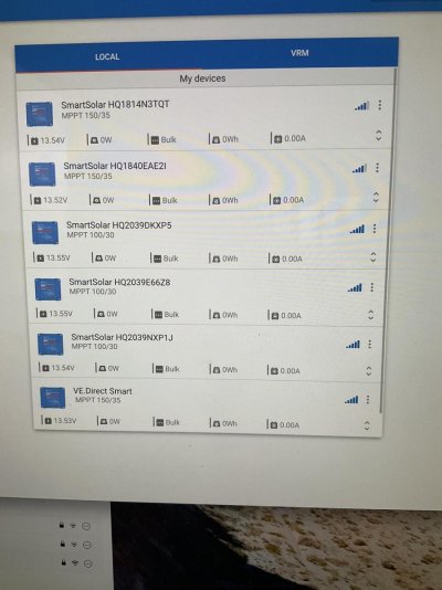
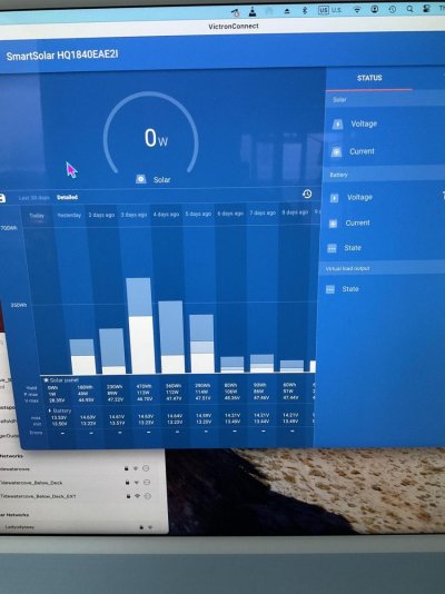
The charge goes smoothly and I can monitor on the Victron app all the MPPT chargers. I have 6, one for each panel. They are a mix of 150/35 and 100/30 charge controllers. To complete the charge of the bank takes about 2-3 hours and all chargers show 14.6V and practically no more charging occurs.
However, the SOC of the bank is slowly going down. I monitor this with Mastervolt EasyView display, which is connected to a MasterShunt with a 350A fuse. In two days, the SOC went down to 55%.
The Victron MPPT chargers allow customization and they are all set to charge to 14.6V
The Mastervolt does not allow any customization for lithiums, but gives me monitoring feature.

The explanation I am looking for is why the batteries go down, when the panels are still providing?
Is it because the Victron and Mastervolt understand things differently? Can it be that the Mastervolt monitoring is not accurate, because the batteries are not from Mastervolt?
My original hope was to have the solars always on and charge the batteries daily and avoid using the Mastervolt charging feature, when I am away from the boat for longer period.

Yesterday, I let the batteries go down the 71% SOC. The solar panels were charging, but it still went down. When turned the Mastervolt charger back from shore-power, the SOC started to climb and in few minutes jumped to 100%. This tells me that something is not sensing things accurately.
I did order another monitoring device from the battery manufacturer and it is on its way. I want to see what will that show on the SOC?
 
This should be a simple case of monitoring the amps out real-time from the house loads and measured amps into the system from the solar panels…

We are now into November. The output from solar should be down considerably at this time of year. At least it is at my latitude (49.3 degrees north). I would not get much out of my solar this time of year.

Jim
 
Last edited:
SOC can be frustrating. Probably one of the least understood readings to many. If all batteries reach 14.6 then you are at or darn near 100% SOC. Not sure without a full wiring diagram but whatever you use to read SOC needs to be reset to 100% at this point. Most systems have a programmable voltage setting and will reset automatically when Batts reach this voltage. Then assuming all current is passing through your shunt SOC should increase or decrease based upon the net current flow. I have found in most cases where SOC is not making sense some current is not flowing through the shunt and thus not being measured and factored into the SOC. I would start by reviewing that all DC grounds are running through your shunt. This would include all the MPPT grounds on all solar converters, all DC load fed from the batteries and the DC ground on your inverter/charger. I had a similar issue and found a few stray grounds that resulted in incorrect SOC. SOC is nothing more than a calculation of amps in and amps out, divided by the total capacity of the battery. And this calculation assumes the batteries start at 100%. You can estimate SOC based upon resting voltage of the battery bank but that is less precise.
 
Got it. I will inspect this tomorrow.

I still don’t understand the quick jump to 100% once the Mastervolt charger activated. Like I said, it was down to 71% having only the MPPTs charging the system all day and reaching the 14.6V by noon. In the evening, when the solar charging was off due to lack of light, I turned the shorepower charging back and after a very short charging, the SOC was showing 100%.
 
Maybe it was not really 71% to begin with? If at noon the voltage was 14.6 the SOC should have read 100%. Do you know what it read at that point? The only way to get a solid reading is to get the batteries fully charged and then make sure SOC reads 100%. Hard to explain in the thread but I am guessing when you turned on your charger it brought the bank to full charge voltage setting (described in my prior post) that triggered the reset of SOC to 100%.
 
Are you measuring solar output, or net amps into the battery? Sounds like you have two shunts, one from Mastervolt and one from Victron. How is all this wired up?


I can't believe that MasterVolt doesn't allow adjustment of the shunt. It would rarely work correctly without it. Is there some "Installer Mode" in the Master Adjust software that you need to access?
 
The Victron controllers will give you the daily output from the panels, add that up to see what you’re actually putting into the batteries.
Maybe your house loads are larger than you think?
 
We are now into November. The output from solar should be down considerably at this time of year. At least it is at my latitude (49.3 degrees north). I would not get much out of my solar this time of year.


Maybe this is a big part of it, since JD and Leo are both in Vancouver ?

-Chris
 
Are the solar charge controllers connected to the shunt properly, or are they bypassing it and going directly to the batteries? That would cause the shunt (and therefore SoC calculation) to not know about the incoming solar power.
 
Let me post some pictures from this morning and I will answer all the questions, too.

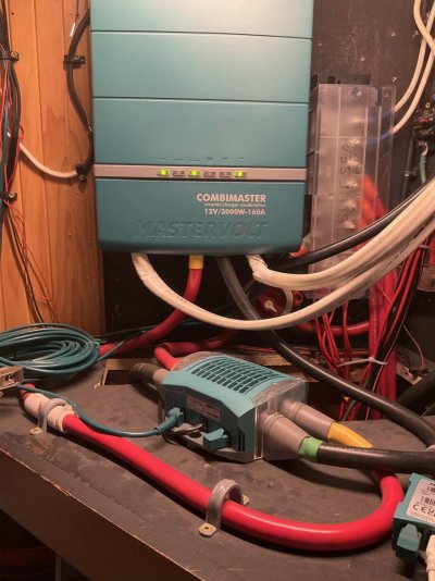
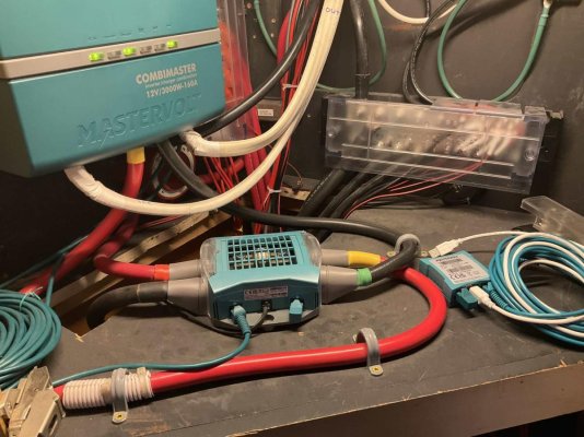
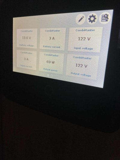
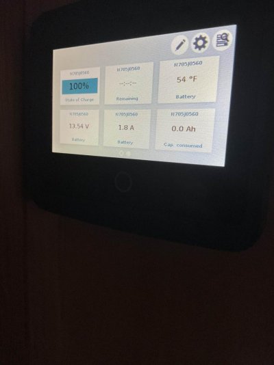
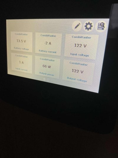
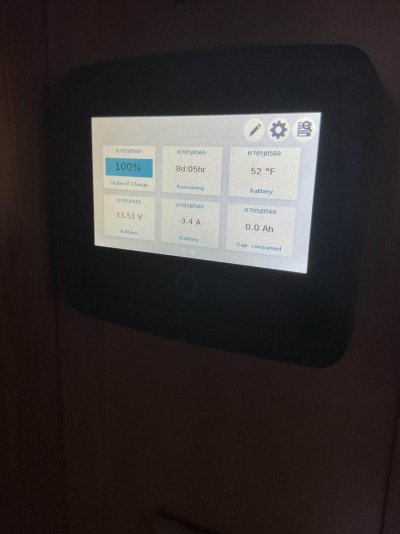
The photos show the EasyView from Mastervolt, fully charged batteries, charger on. I will turn off the charger now, since the solar controllers just came alive due to some light. An hour from now, I will take more pictures to show you how the SOC is going down, despite the solar charging.

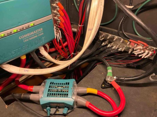
The solar controllers are connected to the batteries directly with a large busbar. All DC connections go through this busbar. Same with the ground connections through another busbar.

The Mastervolt shunt is between the inverter/charger and the busbars. There is no shunt for the solar controllers.

EasyView reads directly from the Combimaster and the chain is terminated at the shunt.

The total gain yesterday from all the solar controllers was 590 Wh. I just added up from each MPPT.

Even with cloudy days, the batteries reach 14.6V in couple hours, since my house load is not significant. My appliances are brand new and very efficient on the AC side. The DC load is mainly bilge vent and a dehumidifier. Diesel furnace circulation pumps are used only in the evening. Cooking is with gas. Espresso machine is only while the shore power is on.

Yesterday the inverter was off and the shore power comes in through the transfer switch at 30A. Meaning, any AC load should not affect the battery use.
 
Are the solar charge controllers connected to the shunt properly, or are they bypassing it and going directly to the batteries? That would cause the shunt (and therefore SoC calculation) to not know about the incoming solar power.

That means do you have the negative connection from the solar controller on the load side of the shunt, not the battery side.
 
IMG_0294.jpgIMG_0293.jpgIMG_0292.jpgIMG_0291.jpgIMG_0290.jpgIMG_0289.jpgIMG_0288.jpgIMG_0287.jpg
 
Last edited:
That means do you have the negative connection from the solar controller on the load side of the shunt, not the battery side.


The solar controllers are connected to the busbars directly.
The shunt is connected to the busbars on one end and to the inverter/charger on the other end. Cables are 4/0 awg.
 
The solar controllers are connected to the busbars directly.
The shunt is connected to the busbars on one end and to the inverter/charger on the other end. Cables are 4/0 awg.


That's your problem. If you want to accurately measure SoC, then absolutely everything has to go through the shunt. Otherwise it doesn't see all of the power going in and out of the batteries and there's no hope of accurately determining SoC.
 
That's your problem. If you want to accurately measure SoC, then absolutely everything has to go through the shunt. Otherwise it doesn't see all of the power going in and out of the batteries and there's no hope of accurately determining SoC.


I see. That makes sense.
What is the proper wiring in this situation? Another bus for the solar controllers and combined with the shunt in cables?

Does this mean that the batteries were actually not depleted in reality?
 
Last edited:
I see. That makes sense.
What is the proper wiring in this situation? Another bus for the solar controllers and combined with the shunt in cables?


Everything (inverter, solar controllers, loads, etc.) should ground to a bus bar. Then it should be connected as bus bar -> shunt -> battery negative. That way all loads ground through the shunt and it can meter all power flow in and out of the batteries.
 
Everything (inverter, solar controllers, loads, etc.) should ground to a bus bar. Then it should be connected as bus bar -> shunt -> battery negative. That way all loads ground through the shunt and it can meter all power flow in and out of the batteries.


Got it.
What about the positive side?
 
Got it.
What about the positive side?


The shunt should only be on the negative side, so it has no effect on how you wire the positive side.
 
See post #3 :) all ground (DC negative) connections must pass through the shunt.
 
Update.

I have changed the wiring as it was recommended.

MasterShunt

Battery side
- Negative has all charge controllers and battery negative cables from the bus bar.
- Positive has all the charge controllers and battery positive cables from another bus bar.

Load side
- Negative has the boat’s negative + Combimaster negative jointly connected.
- Positive has Combimaster positive connected.

Combimaster + EasyView + MasterShunt are networked for monitoring.
I have taken down the numbers during the day to demonstrate the SOC is still going down, regardless of the solar charge.

I started with turning off shore-power completely and activated the inverter. Only a 110V fridge and freezer, computer, phone chargers are running during the day.
EasyView shows between 7-12A house draw from the batteries. Varies based on what turns on.

Victron monitor software data:
11 a.m. some sun, foggy air, SOC 98%
Battery voltage is 14.58-14.61V
Watts; 21, 33,16,5,5,39
Amps: 1.4, 2.2, 1.1, 0.3, 0.3, 2.5 = 7.8 amps
01:00 p.m. partly sunny, SOC 93%
Battery voltage is 14.58-14.60V
Watts; 51, 61, 44, 32, 32, 52
Amps: 3.3, 4.1, 2.8, 2.1, 2.2, 3.2 = 17.7 amps
01:30 p.m. sunny sky, SOC 93%
Battery voltage 14.58-14.61V
Watts; 36, 46, 32, 19, 16, 51
Amps: 2.3, 3.0, 1.7, 1.3, 1.3, 3.4 = 13.0 amps
02:30 p.m. cloudy sky, SOC 91%
Voltage same
Watts; 51, 59, 29, 27, 29, 27
Amps: 3.6, 3.8, 1.9, 1.7, 1.9, 1.9 = 14.8 amps
Now, at 03:45 p.m. the SOC is down to 87%

Once I have my other battery monitoring device from the battery manufacturer, I will post measurements again.
 
Update.

I have changed the wiring as it was recommended.

MasterShunt

Battery side From battery negative to shunt, which may be directional?
- Negative has all charge controllers and battery negative cables from the bus bar. From shunt to bus bar?

- Positive has all the charge controllers and battery positive cables from another bus bar. No, it should be from bat+ to fuse to +busbar, charge controllers?

Load side From battery after shunt?
- Negative has the boat’s negative + Combimaster negative jointly connected.
- Positive has Combimaster positive connected. where is the fuse
..............................................................
Does not sound right.
 
Recently I finished my solar panel installation. I have 6 panels total. 2 375W and 4 220W bifacial.
Once everything was connected, I wanted to test how long will it take to charge the batteries. These are lithiums, 4x170Ah=680 Ah total, with built in BMS by the manufacturer. The recommended voltage by the manufacturer is 14.6V. All levels, bulk/absortion/float.
The charge goes smoothly and I can monitor on the Victron app all the MPPT chargers. I have 6, one for each panel. They are a mix of 150/35 and 100/30 charge controllers. To complete the charge of the bank takes about 2-3 hours and all chargers show 14.6V and practically no more charging occurs.
However, the SOC of the bank is slowly going down. I monitor this with Mastervolt EasyView display, which is connected to a MasterShunt with a 350A fuse. In two days, the SOC went down to 55%.
The Victron MPPT chargers allow customization and they are all set to charge to 14.6V
The Mastervolt does not allow any customization for lithiums, but gives me monitoring feature.

The explanation I am looking for is why the batteries go down, when the panels are still providing?
Is it because the Victron and Mastervolt understand things differently? Can it be that the Mastervolt monitoring is not accurate, because the batteries are not from Mastervolt?
My original hope was to have the solars always on and charge the batteries daily and avoid using the Mastervolt charging feature, when I am away from the boat for longer period.

Yesterday, I let the batteries go down the 71% SOC. The solar panels were charging, but it still went down. When turned the Mastervolt charger back from shore-power, the SOC started to climb and in few minutes jumped to 100%. This tells me that something is not sensing things accurately.
I did order another monitoring device from the battery manufacturer and it is on its way. I want to see what will that show on the SOC?

You have some interesting posts. Not sure what's going on, but here are a few observations: with the solar on, and the SOC dropping to 55%, the issue is with the measurement, not the true SOC. When you bring the combimaster on line and it goes to 10o% quickly, that is because it is measuring tail current ( might be called return amps in Master Adjust) as one of its parameters. That is, the amps in are dropping to a small percentage of total capacity because the batteries are fully charged and can't take any more.
As one responder mentioned, you likely have a wiring issue such that current from the solar is getting to the batteries differently than current from the charger
A side comment, the charger will get the batteries to 14.6 well before you reach 100% SOC. The charger switches from current limited( bulk) to voltage limited( absorb) when the batteries get to 14.6.
 
Does not sound right.


MasterShunt manual calls the left side ‘ Battery side ‘ and the right side ‘ Load side ‘.

So:

Battery negative - bus bar - shunt ‘ battery side ‘ negative - shunt - shunt ‘ load side ‘ negative - negative MasterVolt charger.

Battery positive - bus bar - shunt ‘ battery side ‘ positive - shunt, inside 350A fuse - shunt ‘ load side ‘ positive - positive MasterVolt charger.
 
The fuse is inside the shunt.
 
........................
A side comment, the charger will get the batteries to 14.6 well before you reach 100% SOC. The charger switches from current limited( bulk) to voltage limited( absorb) when the batteries get to 14.6.

also 14.6v can be measured on either side of the shunt.
The mastervolt shunt 500 does have designated terminals from battery and to load for both pos and neg.. reverse hookup will report reverse current flow.
 
MasterShunt manual calls the left side ‘ Battery side ‘ and the right side ‘ Load side ‘.

So:

Battery negative - bus bar - shunt ‘ battery side ‘ negative - shunt - shunt ‘ load side ‘ negative - negative MasterVolt charger.

Battery positive - bus bar - shunt ‘ battery side ‘ positive - shunt, inside 350A fuse - shunt ‘ load side ‘ positive - positive MasterVolt charger.

You posted as I wrote last one. You just described the incorrect wiring.
Correct wiring is from battery +/- to shunt then to bus bars +/- is correct
 
soc dropping to 55%, the issue is with the measurement, not the true soc. When you bring the combimaster on line and it goes to 10o% quickly, that is because it is measuring tail current

i think you are correct but i cannot prove it.


As one responder mentioned, you likely have a wiring issue such that current from the solar is getting to the batteries differently than current from the charger

the bus bar has all those connection in one place.


.


IMG_0389.jpg
 
As one responder mentioned, you likely have a wiring issue such that current from the solar is getting to the batteries differently than current from the charger.

IMO, the positive on the MPPT should be connected to the same stud as the charge controller…or eventually connect to the same positive connection to the bank.

Jim
 
Back
Top Bottom