Why Was Inverter Wired This Way?

The friendliest place on the web for anyone who enjoys boating.
If you have answers, please help by responding to the unanswered posts.

Codger2

Guru
Joined
Oct 11, 2007
Messages
6,691
Location
US
Vessel Name
Circuit Breaker
Vessel Make
2021..22' Duffy Cuddy cabin
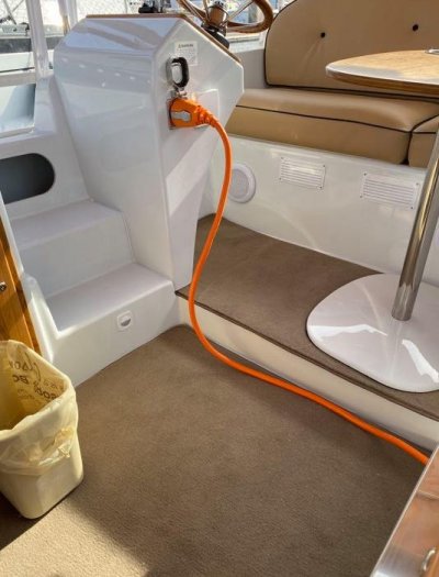
My Duffy/Cuddy Cabin is now one week old and I am finished with trying to understand Duffy's thinking when it comes to the installation of the inverter. (example) My boat has 4- I20-30amp receptacles of which only one is hot when on shore power. The other 3 are hot only when the inverter is switched to on. My previous experience with the last 5 boats was that all circuits were hot when on shore power and only those designated were hot when on the inverter. This means that should I desire to plug a 120v appliance into one of the 3 outlets in question while in the slip, I must have the inverter on.?????
 

Attachments

  • Night lighting.jpg
    Night lighting.jpg
    72.6 KB · Views: 72
  • plugged in to pedistal.jpg
    plugged in to pedistal.jpg
    57.5 KB · Views: 62
My Duffy/Cuddy Cabin is now one week old and I am finished with trying to understand Duffy's thinking when it comes to the installation of the inverter. (example) My boat has 4- I20-30amp receptacles of which only one is hot when on shore power. The other 3 are hot only when the inverter is switched to on. My previous experience with the last 5 boats was that all circuits were hot when on shore power and only those designated were hot when on the inverter. This means that should I desire to plug a 120v appliance into one of the 3 outlets in question while in the slip, I must have the inverter on.?????


First question would be what make and model inverter. If it’s an inverter only, then it would be typical for it to not include provision for an AC input and transfer switch. If an inverter/charger then an integral transfer switch is common.

It sounds like you might have an inverter only.
 
sounds like you do not have shore power going through the inverter to the inverter only plugs. Is it and inverter or an inverter/charger?
 
I would bet that that inverter has a transfer switch that will pass through shore power to the 3 circuits so you don't have to use the batteries to power the inverter.

Look on the main panel. Is there a breaker that says inverter. If not maybe the installer didn't hook up shore power to the inverter or possibly the inverter doesn't have a transfer switch. But that is a poor choice for an inverter. If so as you note you always have to use the batteries and inverter to power those three circuits.

It is also possible to wire the inverter from the main AC breaker if it is 30A. But that isn't as good a wiring choice as using a spare breaker dedicated to the inverter.

Look in the Library (top right icon on this page) for an article that talks about splitting the A/C buss to accommodate an inverter. That is the best way to wire it if it has a transfer switch.

BTW congratulations on your new Duffy build. Those are great little boats. I rented one for an afternoon cruising Newport Beach harbor.

David
 
I'm guessing the inverter doesn't include a charger and transfer switch. The boat is electric and I'm guessing may not be 12 or 24 volt and probably has a charger specific to the engine battery bank, not an off the shelf inverter / charger like a Magnum Energy.

Ted
 
My guess too.
A manual transfer switch should then be installed, switch either shore or inverter
 
Yeah!!!!

Sometimes great expectations from inverters especially those sold specifically for use in vehicles.

The problem is they ARE NOT designed with internal heavy expensive isolation output transformers. The gutcha here is when connected to shore power or an internal generator where the grounded conductor and the grounding conductor are tied together. Those inverters can last years if properly used and they MUST be isolated from the boat's grounding system.

Consider an electrical schematic that resembles the letter H where the load is connected in the middle of the bar in H.

+170V
__|__
| |
\ |
|-**-|
| \
|___ |
|
0 Volts


+170V
__|__
| |
| \
|-**-|
\ |
|___ |
|
0 Volts


This is the standard so called H bridge with the ** being the load. Notice that current each side of the load is alternately connected to 170V depending on which switch is closed and the switches close alternately at 60 times per second. NEVER IS THE OUTPUT TERMINALS CONSTANTLY TIED TO GROUND as house hold power is via its grounded conductor. IF you tie one side of your inverter's output to ground you create a short circuit and possibly destroy your inverter.

SORRY...........the STINKING system will not show my switches properly. Please Google an H bridge to get a better understanding

or

https://en.wikipedia.org/wiki/H-bridge
 
Last edited:
My previous experience with the last 5 boats was that all circuits were hot when on shore power and only those designated were hot when on the inverter. This means that should I desire to plug a 120v appliance into one of the 3 outlets in question while in the slip, I must have the inverter on.?????


Ask Duffy?

-Chris
 
Not sure why charging with shore power and darwing 110V via another outlet powered by the inverter is not OK?

Sounds fine to me. Plus you can draw more than just through a 30A cord...hard to imagine on that boat.

The house bank on that dwarfs most trawlers here.
 
This is all speculation until the OP tells us if the equipment in question is an inverter or an inverter/charger and the make and model of the unit.

BTW, I seriously doubt that the boat has 4 120V 30A receptacles as stated.
 
Not sure why charging with shore power and darwing 110V via another outlet powered by the inverter is not OK?

Sounds fine to me. Plus you can draw more than just through a 30A cord...hard to imagine on that boat.

The house bank on that dwarfs most trawlers here.


Other than a little efficiency loss, I agree it's no big deal. Lots of boats take exactly this approach to operate with non-native power, i.e. 50hz shore power for a 60hz boat, and vice versa.
 
By only switching on the inverter and plugging into it when in use ,,the hassles of not connecting the neutral from the ground at inverter time is gone.

Smart , easy, cheap, no learning curve.
 
First question would be what make and model inverter. If it’s an inverter only, then it would be typical for it to not include provision for an AC input and transfer switch. If an inverter/charger then an integral transfer switch is common.

It sounds like you might have an inverter only.
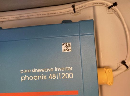
I finally got the make and model number off the unit and it appears that I have an inverter only! It's a Victron 48/1200 and I got this statement off their site.


When it comes to "electrical matters" I check out. 5 of my last 10 boats had inverters (Inverter/Chargers?) that had power at all receptacles when on shore power & only had power at pre-determined outlets when on the inverter. That is what confused me about this Duffy. :whistling::facepalm::hide:
 

Attachments

  • Screen Shot 2020-11-29 at 6.45.38 AM.png
    Screen Shot 2020-11-29 at 6.45.38 AM.png
    31 KB · Views: 27
By only switching on the inverter and plugging into it when in use ,,the hassles of not connecting the neutral from the ground at inverter time is gone.

Smart , easy, cheap, no learning curve.
So easy, it confused me! :blush:
 
Not sure why charging with shore power and darwing 110V via another outlet powered by the inverter is not OK?

Sounds fine to me. Plus you can draw more than just through a 30A cord...hard to imagine on that boat.

The house bank on that dwarfs most trawlers here.


Then I suggest that you try it and see why for yourself. If that ‘’other outlet’’ has one side of the line tied to the boat’s neutral be sure to let us know what happens.

Of course, if the outlet you refer to is dedicated specifically to the inverter and not connected to the boat’s electrical power circuits that would not be an issue.
 
Last edited:
Then I suggest that you try it and see why for yourself. If that ‘’other outlet’’ has one side of the line tied to the boat’s neutral be sure to let us know what happens.

Of course, if the outlet you refer to is dedicated specifically to the inverter and not connected to the boat’s electrical power circuits that would not be an issue.

Well, hate to get technical on you...but I didn't wire the boat, Duffy did and I bet they know what they are doing, designing and building electric boats....... and the OP said it works just fine...he just didn't understand why it was wired that way.

So, not being the genius everyone else seems to be...I don't try and figure out what is wrong with a system that seems to work. One BIG reason I don't is because I am not there to figure out what wire goes where.
 
WALT...it may be similar to my boat in that all but one of my outlets runs through the inverter to a sub-panel just for outlets. My odd ball outlet is reserved for high amperage items.

Because my inverter does have a pass through relay, the "outlet" panel can be powered either way....from shore or the batteries inverted.

My only guess is they saved some bucks on not installing a switching relay or inverter with one built in. But I also see the simplicity in their design if its what I am guessing.
 
If your inverter has an internal power transformer there should be no problem. Now as to experts.....Gees., after years of reading your posts, I thought you were the resident know it all and now you are trying to disappoint me?

There are quite a few topics I don't comment on or try and post schematics that may or may not have anything to do with the thread topic....not because of the differences in inverters, but the unknown of how the boat is wired.

Again I am not trying to cause confusion in a topic by taking it into what ifs...I was just trying to answer Walt's dilemma.
 
My boat has 4- I20-30amp receptacles of which only one is hot when on shore power. The other 3 are hot only when the inverter is switched to on.


I finally got the make and model number off the unit and it appears that I have an inverter only! It's a Victron 48/1200 and I got this statement off their site.

sounds like you do not have shore power going through the inverter to the inverter only plugs. Is it and inverter or an inverter/charger?
If you want all plugs to work on shore power AND/OR inverter the plugs need to be wired through a manual transfer switch.
Or you turn the inverter while plugged in all the time you need a non shore power plug.
 
there are quite a few topics i don't comment on or try and post schematics that may or may not have anything to do with the thread topic....not because of the differences in inverters, but the unknown of how the boat is wired.

Again i am not trying to cause confusion in a topic by taking it into what ifs...i was just trying to answer walt's dilemma.


Peace! I just deleted my controversial post
 
Last edited:
WALT...it may be similar to my boat in that all but one of my outlets runs through the inverter to a sub-panel just for outlets. My odd ball outlet is reserved for high amperage items.

Because my inverter does have a pass through relay, the "outlet" panel can be powered either way....from shore or the batteries inverted.

My only guess is they saved some bucks on not installing a switching relay or inverter with one built in. But I also see the simplicity in their design if its what I am guessing.
That's what I've been thinking. Like I said, the boat works well and if I plug an appliance into one of the 3 outlets, I just have to turn the inverter on and there is a toggle switch to do that. It's no big deal!
 

Attachments

  • Victron Phoenix 48:1200 Inverter.jpg
    Victron Phoenix 48:1200 Inverter.jpg
    48.9 KB · Views: 22
Yeah!!!!

... they MUST be isolated from the boat's grounding system.

Consider an electrical schematic that resembles the letter H where the load is connected in the middle of the bar in H.

+170V
__|__
| |
\ |
|-**-|
| \
|___ |
|
0 Volts


+170V
__|__
| |
| \
|-**-|
\ |
|___ |
|
0 Volts


This is the standard so called H bridge with the ** being the load. Notice that current each side of the load is alternately connected to 170V depending on which switch is closed and the switches close alternately at 60 times per second. NEVER IS THE OUTPUT TERMINALS CONSTANTLY TIED TO GROUND as house hold power is via its grounded conductor. IF you tie one side of your inverter's output to ground you create a short circuit and possibly destroy your inverter...

This is incorrect. The bridge operates on the 'Hot' wire only. The 'Neutral' wire is a grounded conductor, as in household systems. In an Inverter/Charger, the transfer relay disconnects the ground to neutral bond when transferred to incoming power and connects it when inverting. In an Inverter only the G and N are permanently connected. In either case, the output neutral conductor must be kept isolated from the vessel neutral buss when any other source is providing power. Otherwise, a ground-loop will exist and current will flow in the grounding circuit. This is a portion of the load current which should all flow through the N wire but is finding a shared path through the improper G-N connection. Voltage produced by this fault current is impressed on underwater metal parts and causes corrosion and premature depletion of anodes.
 
Back
Top Bottom