ABYC Lithium-Ion standard compliance

The friendliest place on the web for anyone who enjoys boating.
If you have answers, please help by responding to the unanswered posts.
Looks Like We Missed the E11 Requirement

Good stuff Peter.

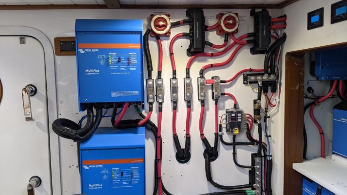
A couple years ago we built a new L-I house, removing the AGM bank. It has split banks with external BMS for each. We assumed that each BMS would serve as the battery bank disconnect.

An overview photo of the system is attached. Both banks come together on the POS MAIN busbar in the upper right hand corner. To comply with E11, looks like we have room to add a manual disconnect switch for each bank.

Thanks for the heads up.

Alex
 

Attachments

  • Wild Blue 24v 30kw L=I Main Bank.jpg
    Wild Blue 24v 30kw L=I Main Bank.jpg
    112 KB · Views: 56
Regarding the disconnect: One strategy I am looking at is to have an aux bank of AGM to act as a current dump and secondary backup in the event of a problem disconnecting the LFP. The only sure way I can see to do this is the connect alternator sources to both banks via a FET isolator, bypassing the manual disconnects. That insures a place for the energy to go regardless of the manual or BMS disconnect state. In theory no current can flow from the batteries towards the alternator and associated wiring. In the eyes of the ABYC, does this defeat the manual disconnects? A dangerous fault would require both a short in the isolator -> alternator wiring and a faulty FET that is shorted. It does violate the recommendation against mixed chemistry, but in this particular case that is not a concern.
 
Regarding the disconnect: One strategy I am looking at is to have an aux bank of AGM to act as a current dump and secondary backup in the event of a problem disconnecting the LFP. The only sure way I can see to do this is the connect alternator sources to both banks via a FET isolator, bypassing the manual disconnects. That insures a place for the energy to go regardless of the manual or BMS disconnect state. In theory no current can flow from the batteries towards the alternator and associated wiring. In the eyes of the ABYC, does this defeat the manual disconnects? A dangerous fault would require both a short in the isolator -> alternator wiring and a faulty FET that is shorted. It does violate the recommendation against mixed chemistry, but in this particular case that is not a concern.


I believe the intent of the disconnect is to be as close to the batteries as possible, and before any loads or charging sources. So I would feed in any charging source into the load side of the disconnect, not the battery side. You companion AGM is essentially creating another battery bank, so that should also have a fuse and disconnect, just like the LFP bank.


If you are suggesting somehow paralleling the AGM and LFP banks, it is recommended that you NOT do that. And the ISO pre-standard outright prohibits it.


A drawing would help ensure I'm following what you are contemplating.
 
I take it back. Here's what E-11 says regarding battery disconnect switches. So it looks like your charging source is allowed on the battery side of the disconnect switch. That said, I would keep any connected devices on the battery side to an absolute minimum. A bilge pump and small shore power charger I could see, allowing you to otherwise shut off the battery while away from the boat. But you could argue that an Inverter/charger is "Battery Charging Equipment", and I definitely would not put that on the battery side of the disconnect. Nor would I put an alternator output on the battery side.


11.6.1.2 BATTERY SWITCH
11.6.1.2.1 A battery switch shall be installed in the positive conductor(s) from each battery or battery bank with a CCA rating greater than 800 amperes or 100 Ah if CCA is unavailable.
EXCEPTION: Trolling motor conductors connected to dedicated trolling motor batteries provided with overcurrent protection at the battery and a manual means of electrical disconnect separate from the trolling motor controls.
NOTES: Conductors supplying the following may be connected to the battery side of the switch: 1. Electronicequipmentwithcontinuouslypoweredmemory;
2. Safetyequipmentsuchasbilgepumps,alarms,COdetectorsandbilgeblowers;
3. Batterychargingequipment;

4. Impressedcurrentsystems.
11.6.1.2.2 A battery switch shall be mounted in a readily accessible location as close as practicable to the battery.


This is the sailboat and it has a complicated DC system. 24V, with 12V engine system, two 24 alternators, and two panels, one for most loads and another Keep Alive panel intended to be left powered in storage. Both panels have a 1-2-BOTH-OFF switch. Banks 1 & 2 have both been AGM and have been run typically in BOTH position.

The proposed change is to keep a bank 2 as a small AGM bank, and change bank 1 to LFP. Normal operation would use only bank 1, i.e. both switches in position 1. In the berth I'd switch the main panel off, and the Keep Alive panel to 2. That would isolate the LFP, and allow the AGM to stay float charged from the solar (which comes through the Keep Alive) as well as run the bilge pumps, 12V DC-DC charger, etc.

Question is, what happens when the LFP BMS disconnects? Right now, the alternators are connected on the panel side, so if one were to switch that switch to OFF, bad things happen. But it requires me doing that, and I wouldn't. If the BMS disconnects, the same bad things happen without my doing anything. The idea of dumping the energy into the AGM bank 2 only works if the switch is always in BOTH (now paralleling the chemistries for sure), or the charge current comes through the isolator bypassing the switch. That effectively parallels them only for charging from only the alternators - not that bad a thing on a sailboat where the engine is not run for long periods often. 28.4V won't hurt the AGMs even for hours, as long as it isn't 24/7. The switch could be changed to bank 2 to restore power from the AGM bank in the event of an LFP fault, and would work normally.

The isolator could be wired with one output to the AGM bank 2, bypassing the switch, and the other output to the panel side of the switch which would eliminate the bypass on the LFP bank 1.

All of this presupposes that the AC line charger (Mastervolt 100A) has fast enough response to not create much of a spike in the event of a BMS disconnect. I haven't actually tested that, and it isn't spec'd. Otherwise the same thing would have to be done there, even though the charger is rarely used.
 
@DDW #36
To answer your questions:
1. What type of LFP batteries do you have; e.g., drop in, Victron Smart, individual cells?
2. What BMS are you using? Does it produce ATC and ATD signals?
3. Does the BMS communicate with the Mastervolt charger?
 
1. Drop in. Leading candidate are Discover DC12-24, probably 3P.
2. No.
3. No. Charger predates LFP, but is programmable for compatible voltages and phases. No external disable as far as I can tell.

The Discover seem to be high quality, are rebuildable, are individually fused in addition to the BMS, and happen to fit the space available. Victron would require significant rebuild of the whole system, and trap me into Victron for life. Otherwise I like them :). I don't think the Mastervolt 24/100 charger can be updated to communicate with a BMS (short of complete replacement).

With 3 in parallel each with BMS, the likelihood of a BMS disconnect in all three simultaneously is small, but there are scenarios.
 
@DDW #38
I thought I may be able to help but not with the equipment you have chosen. Without an ATC and ATD signal to work with you are into trying to manage with switches/contactors.

IMHO, I am just not a fan of drop in LFP batteries with an internal BMS that doesn't communicate outside of the battery case. They may have a place on bass boats and simple runabouts but as soon as they start being paralleled, I don't think they have a place on a cruising boat.

As a business decision, I won't install drop ins on a boat. I will, and have, installed them in a van but my rationale is if something goes wrong and you lose the bank in an RV, you can pull the van to the side of the road and sort it out. On a boat in the middle of the Gulf Stream, not so much.
 
If it just goes down, that makes the AGM backup bank useful, doesn't it. If it catches fire, different level of problem. I'd say 'drop ins' come in a huge continuum of quality and capability these days. There are a lot - most of them - that I would not consider. The only better maintainable alternative in my opinion is a purpose built external BMS and cells. Otherwise you are hoping that all the different vendor's products communicate correctly with no finger pointing, and that they are still in business for the life of their product - both are rash assumptions in this rapidly evolving market. At least with a drop in, it lifts out as easily as it dropped in.
 
I have setup a lithium 600A bank of three Kilovault batteries last spring. This summer I was more than happy with it. All 3 batteries use a cat5 cable connected to each other acting as one big battery.

What I did is install two battery switches with remote control switches. They are installed by the helm at a arms reach. If for some reason the BMS shuts down I can disconnect the house bank. Then hit the other remote switch and run off the starting bank. Than I can Bluetooth into the batteries to see whats going on.

Just an FYI, the Alt is only charging the starting bank and I am using a DC to DC charger for the house bank. So far so good!!
 
The Kilovault are an example of a 'drop-in' I'd consider using, pretty well thought out and made. But no 24V version.

That strategy - alt charging AGM bank, DC-DC charging LFP, mitigates the BMS disconnect worry WRT the alternator. In my situation not really practical: the alternator produces 280A @24V, there is no reasonably priced DC-DC that can do even a fraction of that. I could go the other way, alt charges the LFP and DC-DC charges the AGM bank. But I do not believe the DC-DC can absorb the energy required to deflux the alternator in the event of a disconnect.

Another strategy might be to have a combiner or contactor parallel the AGM and LFP whenever the engine is running. But that creates a second set of issues so it seemed like the isolator would be simpler.
 
If the BMS can give a warning before disconnect, that can be used to cut the alternator field or tell the regulator to cut the field. If the alternator isn't putting out power when the disconnect happens, it won't be damaged.
 
The Kilovault are an example of a 'drop-in' I'd consider using, pretty well thought out and made. But no 24V version.

That strategy - alt charging AGM bank, DC-DC charging LFP, mitigates the BMS disconnect worry WRT the alternator. In my situation not really practical: the alternator produces 280A @24V, there is no reasonably priced DC-DC that can do even a fraction of that. I could go the other way, alt charges the LFP and DC-DC charges the AGM bank. But I do not believe the DC-DC can absorb the energy required to deflux the alternator in the event of a disconnect.

Another strategy might be to have a combiner or contactor parallel the AGM and LFP whenever the engine is running. But that creates a second set of issues so it seemed like the isolator would be simpler.

There are many devices like as in this link that will protect the Alt. This is just one out of many. https://sterling-power.com/products/alternator-open-circuit-protection-device
 
If the BMS can give a warning before disconnect....
Exactly. Most drop ins don't, and in any case it isn't a perfect solution.
There are many devices like as in this link that will protect the Alt. This is just one out of many. https://sterling-power.com/products/alternator-open-circuit-protection-device

None of those devices mention how much energy they will absorb, and all of them caution that it may not be enough. Also, a one shot deal as they are likely destroyed in the process. This isn't a little Delco alternator, it is a 7KW driven by a power takeoff. Would need two as there are two alternators. So again, not the perfect solution.

A backup AGM bank to dump the energy has several advantages, mainly: it can absorb a lot of energy and is known to work, and it provides a backup for the DC system if the LFP back shuts down, otherwise the boat goes dark. Secondarily in this particular case, it provides a reliable solar charged DC source long term at the dock, which is problematic with LFP.

I'm familiar with all the methods, I think. Thanks for the suggestions, but my question was really a specific one about ABYC, FET isolators, and disconnect switches.
 
I think the splitter idea could work. Just wire it in on the load side of the disconnect switches. You will need to decide which bank will provide the voltage sense point for the alternator regulators, assuming an external regulator. And ensure both banks can handle the voltage range.

To me the best way to do this is with a signal from the BMS. It both provides a damage-free shutdown of alternators, plus a warning and likely avoidance of a battery disconnect. I think it’s a deficiency in BMSes that don’t provide such a signal.
 
I'd agree that it is a deficiency. And pretty much costless for the manufacturers. I'd use it if it were available. An extra light terminal on the battery, could be wire OR'd for parallel setups. The signal probably already exists inside, or could with a few lines of code.
 
Exactly. Most drop ins don't, and in any case it isn't a perfect solution.


None of those devices mention how much energy they will absorb, and all of them caution that it may not be enough. Also, a one shot deal as they are likely destroyed in the process. This isn't a little Delco alternator, it is a 7KW driven by a power takeoff. Would need two as there are two alternators. So again, not the perfect solution.

A backup AGM bank to dump the energy has several advantages, mainly: it can absorb a lot of energy and is known to work, and it provides a backup for the DC system if the LFP back shuts down, otherwise the boat goes dark. Secondarily in this particular case, it provides a reliable solar charged DC source long term at the dock, which is problematic with LFP.

I'm familiar with all the methods, I think. Thanks for the suggestions, but my question was really a specific one about ABYC, FET isolators, and disconnect switches.

I tryed....... But to your point, thats why I went with a DC to DC charger.
I am not in your league or TT's. Just trying to learn.
 
If I had a pre-disconnect warning line out of the drop-in BMS, I could use it to kill the alternator regulator. Then the alternator output could be tied to the LFP bank, and a DC-DC used on the AGM, as you do. I'd still have the AGM bank for the other reasons mentioned, even though there is also a third AGM start bank, 12V, charged through a different DC-DC downconverter. That was necessary because the engine was not practically convertible to 24V.
 
If I had a pre-disconnect warning line out of the drop-in BMS, I could use it to kill the alternator regulator. Then the alternator output could be tied to the LFP bank, and a DC-DC used on the AGM, as you do. I'd still have the AGM bank for the other reasons mentioned, even though there is also a third AGM start bank, 12V, charged through a different DC-DC downconverter. That was necessary because the engine was not practically convertible to 24V.


I don't recall how far down this road you are already, but I would recommend against any drop-in or BMS that doesn't provide such a warning. I just don't think you can build a satisfactory system without it, and instead end up with a pile of work-arounds, none of which you would ever do were it not for a deficient BMS.
 
I'm not far down the road so I may wait. However I view this as not a completely obvious decision. The use of an advanced signal to kill the regulators has its own set of issues, and instead using an isolator as I have proposed has its own advantages. Like anything else in a boat, both are compromises. My main concern in posing the question was: will a get pushback during an insurance survey in the future, if the isolator bypasses the disconnect? It sounds like the ABYC allows this as an exception.

LFP batteries are better in many respects than AGM. One way in which they are clearly inferior is that they, and the installation to support them, are far more complex, and therefore more fragile. With a correctly setup charging system, AGMs are a drop in and forget for life proposition. The ones I'm intending to replace were purchased in July 2005, and when tested last week still have about 70% of label capacity (but higher internal resistance than I'd like). LFP, at this stage at least, become a bit more of a hobby to deal with.
 
Once again it's too bad that the ABYC can't publish these standards.

Two questions:

There was talk about requiring a pre-disconnect warning of 7 seconds or something like it. Do I understand correctly that that is a recommendation, not a requirement?

Same issue on paralleling chemistries - is it prohibited or recommended against?

I am aware of the arguments for such things, but also the difficulty of implementing them in every case.


I really don't see how the 7 second warning of impending BMS disconnect could be implemented. With some good programming some of the scenarios could be covered, like consistently rising temps. But it seems many electrical failures are instantaneous exceedances. In those circumstances going an additional 7 seconds may not be wise, or even possible.

I think a better way would be warning bars that alert any time a parameter nears an exceedance area or goes outside an optimal range. Somewhat like the Racor vacuum gauge. Yellow, Red and then shut down. That way if something is operating in the yellow, even for minutes or hours, it can be monitored more closely and decisions can be made. Even then many exceedances will be instantaneous. I think this area needs more work. I think it could be a mistake to even float a potential standard unless it is fully workable. I currently do not think this 7 second time constraint is workable and my fear is that Insurance companies use these types of things to deny coverage or pay outs.


It's a bit moot since that got dropped from the requirements, and the recommendation is more generic without any specific time requirement.


That said, the BMSes I've seen with such signals all do it the way you suggest, creating warning bands of one sort or another, and signalling when those bands are crossed. A BMS disconnect comes later.

Good deal. Thanks for all the great info here. Much appreciated.
 
Just an FYI. Not sure if this helps.

From the Kilovault manual. The funny thing is, I can't find the touch screen at their web site.

C
The KiloVault HLX+ BRIDGE is integrated with smart touch screen, management control board, interface ports, and Bluetooth. Through CAN/RS485 communication, it can monitor, manage and control The KiloVault HLX+ series batteries. In multiple battery series-parallel battery bank, there are monitoring, protection and data checking functions, and can use the HLX+ BRIDGE to upgrade the battery firmware. It is commonly used in battery systems of residential storage, RV, Off grid
 
I must be stupid. Read this stuff and remain confused. Most boats want to use LFP for the house bank. Some like to have two house banks for redundancy. Most boats aren’t interested in using LFP for propulsion but some are. Am I to understand the various banks on a boat need to be completely segregated? Key systems are navigation and AP, engine starts and gen start and thrusters to my mind. The rest can be supplied by a house bank or several house banks. So does this mean if you’re going with PB for the key functions they need to be charged by their own sources ( alternators, wind/solar, shore power inverter/chargers). If you’re going with Li for those functions do those batteries need to be segregated from start to finish from the house bank as well?
How do you avoid a violation using a charging source like solar to charge all your various batteries and banks?
Apologize in advance for my lack of sophistication.
 
LFP batteries are better in many respects than AGM. One way in which they are clearly inferior is that they, and the installation to support them, are far more complex, and therefore more fragile. With a correctly setup charging system, AGMs are a drop in and forget for life proposition. The ones I'm intending to replace were purchased in July 2005, and when tested last week still have about 70% of label capacity (but higher internal resistance than I'd like). LFP, at this stage at least, become a bit more of a hobby to deal with.

Valid points for some to keep in mind. Delfin installed a very simple system a few years ago where owner manual inputs rather than auto switching is utilized.

In your case DDW, do you spend enough time at anchor where the advantages of LFPs are clearly demonstrated? Your on engine generator is quite a beast likely topping up your AGMs after but a few hours of cruising.
 
I must be stupid. Read this stuff and remain confused. Most boats want to use LFP for the house bank. Some like to have two house banks for redundancy. Most boats aren’t interested in using LFP for propulsion but some are. Am I to understand the various banks on a boat need to be completely segregated? Key systems are navigation and AP, engine starts and gen start and thrusters to my mind. The rest can be supplied by a house bank or several house banks. So does this mean if you’re going with PB for the key functions they need to be charged by their own sources ( alternators, wind/solar, shore power inverter/chargers). If you’re going with Li for those functions do those batteries need to be segregated from start to finish from the house bank as well?
How do you avoid a violation using a charging source like solar to charge all your various batteries and banks?
Apologize in advance for my lack of sophistication.


I'm not quite following how or why you are splitting things up as described.


I'd say the nominal arrangement is to replace the house bank with LFP, leaving all loads unchanged.


- Previous charging systems that simply bridge start and house banks (VSRs, etc) would need to be reworked since you shouldn't bridge dissimilar battery chemistries (ABYC recommends against, and ISO draft prohibits). There are a number of ways to then divi up charging between the two types of banks, and I can go into them separately if there is interest.


- Because LFP batteries all require a BMS, and because driving the battery into an unsafe condition will cause the BMS to disconnect, you arguable have a greater probability of your house bank disconnecting. Lead house banks can disconnect too if their fuse blows. It's also very important to understand that a BMS will never disconnect unless something has gone wrong and the battery is being driven to an unsafe condition. If that happens with lead, you just fry the batteries or burn stuff up or douse everything is acid, but you house bank will probably continue to produce power long enough for you to nice that you have a big problem. In contrast, and LFP bank will disconnect rather than burn up or spew acid, and that means lights out for anything on the house bank. This probably includes electronics. Because of this, ABYC recommends that you consider this and provide backup power of some sort if you feel it's needed.


- Some LFP batteries (most drop-ins) have BMSes with limited current carrying capacity. As such, they are not suited for heavy, burst loads like engine starters and thrusters. Note that it's not an LFP limit - quite the opposite as LFP can delivery huge whollops of power with joy. It's the BMS used in lower-end batteries that will pop if there is a huge current draw. This is why most all systems retain lead start batteries, and also might be a cause to move thrusters from the house bank to a start bank. if it isn't already.


OK, there's a long answer to a questions I'm not sure I understood in the first place, but I hope it helps.
 
It helps some. Appreciate you taking the time.

Could you expound on

- Previous charging systems that simply bridge start and house banks (VSRs, etc) would need to be reworked since you shouldn't bridge dissimilar battery chemistries (ABYC recommends against, and ISO draft prohibits). There are a number of ways to then divi up charging between the two types of banks, and I can go into them separately if there is interest.

It’s here I’m confused. On prior boats had wind and solar. On this one just a large solar array. Know the risk is overcharging. Degassing Pb or injuring Li. For both wind and solar excess production was eliminated by high resistance coils releasing the energy as heat. What PB and Li will accept and tolerate is different. How is the energy coming in divided? How does one keep energy coming in to the Pb batteries to top off that last little bit to get them at 100% soc when the Li needs no more? How is the decision made to give what amount of energy to each different chemistry?
 
- Because LFP batteries all require a BMS, and because driving the battery into an unsafe condition will cause the BMS to disconnect, you arguable have a greater probability of your house bank disconnecting.
<Snip>. In contrast, and LFP bank will disconnect rather than burn up or spew acid, and that means lights out for anything on the house bank. This probably includes electronics. Because of this, ABYC recommends that you consider this and provide backup power of some sort if you feel it's needed.
.

Mountain out of molehills.
It's pretty simple IMHO

1) set your charger and mppt up so as not to overcharge cells - took about 5 minutes - no reason for BMS to disconnect

2) run multiple batteries in parallel - I built 3 X 280ah @ 24v - 1 battery shuts down for whatever reason I have 2 - 2 shutdown for whatever reason I have 1.
We have ran the boat for a 24 hour cycle on 1 battery during install and it was fine.

It still amazes me how great these things are
Cooked a roast meal in the air fryer last night
Leave everything running 24/7 (multiple 240v fridge freezer, hot water system, PC X 2 etc etc)
Use electric kettle in the morning just now
Batteries are still at 78% at 5:30am
Sun is up, batts will be at 99% by about 11am and I'll be be making 150 lph of water and and no Genset was used for anything.

Could not have dreamed of doing that with AGM.
 
Last edited:

Latest posts

Back
Top Bottom