Alternator advice needed

The friendliest place on the web for anyone who enjoys boating.
If you have answers, please help by responding to the unanswered posts.
Wow so much information. After everything that I've read, I would suspect your internal regulator is not working. First thing to check. Good luck. Jack


Thanks. Before taking it apart, I will replace the belts.
What if the belts are not good anymore and the alternator is slipping a bit? That should interfere with the inside regulator duties. Once the engine has run for a while and everything is hot enough to tighten the belts, the regulator is up to the required rpm and turns the charge up?
Is this a possibility? It is a theory, but I could be wrong.
 
Yes, it is internally regulated. I have not messed around it. It has been like this since install.

The cranking batteries are separated from the house bank. They have their own charger from shore power, and the alternator charge underway. So these batteries are always charged. Plus they are only a year old cranking lead acid batteries.

I don’t think I can have this rebuilt. I could not find anyone in the area, when my previous alternator went out. This one is still working, but I cannot tell, if 100% ?
I don’t mind investing in a new one and keep this as an emergency backup. It would be nicer to have an alternator, which can be adjusted/measured while in use. This one does not.
So, the alternator only charges your starting bank? How is your lithium house bank charged while underway?
 
To the OP, the guy that can get you sorted is not that far away from you. Go to Townsend Electric, 2227 Washington St, Port Townsend. He set up my 3 x 220A Leece Neville alternators in 2012. One is a spare and has never been used.

And yes, you need them (or it I think in your case?) to be externally regulated ( I have a Balmar 612 Dual, you could get a Balmar but a Wakespeed might be an even better option) and have him put an external earth on it as well. Sure, he can test it but I'd be confident that the internal reg in it is now junk and just needs to be ditched.
 
You have a decent alternator from the photo. Leece Neville make decent equipment.

What rpm do you run the engine at? Yes it matters. If an alternator is run to slowly it CANNOT produce its full rated amperage. To see this you need the output curve from Neece Leville. THey used to offer those on their site along with the model descriptions and ratings. In many cases the alternator must be run at at least 2/3 of it rated rpm which is often 10,000-12,000 alternator rpm. So your alternator must be operated at about 7,000 rpm to put out full amperage.
If your engine max rpm is 2,600 rpm then the drive ratio must be about 3:1 or a bit more to get the alternator revving enough to come close to the max. output.

This may explain, at least partly, why the dash voltmeter shows little change for a long time.

If the alternator is spinning to slowly it may be producing only 20% to 25% of its rated amps. THen your operating equipment, VHF, radar, fridge, lights and any other running equipment may be drawing 1/2 of that current.

The result is a SLOW recharge. The other result is that the SYSTEM voltage will take a LONG time to show much change even though there is some recharge going on.

Check the drive ratio between the engine driver pulley and the alternator pulley.

Yes, in this case an external smart regulator will improve the alternator performance however if the drive ratio is to far off it may not help as much as hoped for.

Put a tape across the face, diameter, of the engine drive pulley and across the face, diameter of the alternator pulley and calculate the ratio. Or post the two measurements here for others to calculate. It won't be exact but it will be close enough for these purposes.

The Leece Neville alternators are designed and set up so the "internal" regulator is easily removed unlike many other alternators. It is actually externally mounted. A few screws and some wiring disconnecting and the regulator will come off. No alternator opening up.

Now to muddy things some more there are alternators that are designed for MUCH higher output at not much above an engine idle. They are usually sold for emergency equipment such as fire trucks, EMT busses, ambulances, and so on. But they are quite different in many cases.

Your Leece Neville should be able to do a good job but likely with some changes.

And last but not least you do not need to be running the boat to do some voltage and amperage testing. JUst run the engine at the dock and use a Voltmeter and a clamp on DC ammeter. I emphasize the DC as there are a lot of AC only ammeters which are of no use for this. They MUST be able to read DC and ideally True Sine Wave.
 
Last edited:
And last but not least you do not need to be running the boat to do some voltage and amperage testing. JUst run the engine at the dock and use a Voltmeter and a clamp on DC ammeter. I emphasize the DC as there are a lot of AC only ammeters which are of no use for this. They MUST be able to read DC and ideally True Sine Wave.


Great info, thank you.
A little background. This alternator was installed by a mechanic, when the previous one died. It was the same brand, but 120A. I don’t think the pulley or the belts were changed. It just fit in.
I did not know much about it, so I just trusted the mechanic. He did the replacement completely. I really don’t know when this alternator stopped charging properly.
In the past, I started my main engine directly, without my generator. Not only it sucked down the cranks batteries, but also I could hear wheeling sound, which would go away after few minutes. Sounded like the old cars with worn belts. I have learned, if I start my generator first,this sound would not happen. I suspect the alternator was not overloaded, since the generator provided the power and charged the batteries. So, this was my method to start the main engine and the wheeling sound did not occur anymore.
After I started this thread, my generator was down and I fixed it just yesterday. Today, I did the first measurements on the alternator, following the diagram I’ve posted earlier.
There was no charge from the alternator.
The starting voltage of the crank batteries was 12.8V. After I started the generator, ( shorepower disconnected ) the main engine started, but it took several tries. This is always the case when the engine is not used for a month or so. I am on shorepower most of the time, as I do many projects simultaneously. With the main engine running, the voltmeter in the PH showed a bit above 12V. As I was disconnected from shorepower, I shut down the generator and the voltmeter gauge slowly went into yellow. I went to the engine and measured the batteries. It was 12.45V. I measured the alternator output, but nothing was coming out. This was at 700 rpm on the main. The guide suggests to move the rpm up to 1500, which I did. Still no charge was coming from the alternator.
I run my engine underway between 1500-1600 rpm. This is my cruising speed of 6-7 knots. CAT3306. When the alternator was new, I remember seeing the voltmeter gauge in the green with a healthy voltage.
I also used a digital amp meter on the wires, but nothing was measured. When the generator runs, I can see 14A on the wires.

So, it must be the regulator on the alternator. I am happy to learn that the regulator is easy to remove on these models. The question now is, what shall I replace or remove? Do I just take off the regulator and try to replace it with a new one? Or do I have to remove the alternator completely and take it apart, or take it to a repair shop? Or just get a compatible external regulator in combine it with the alternator?
I do plan to get a better gauge for the pilot house, preferably digital. Balmar solution includes digital display at the regulator for an extra charge. They also sell a remote display, which can be put in the PH. it would be nice to have, but the price is pretty high. Just a simple regulator replacement solution would be cheaper, but less informative for observation during troubleshooting.
 
When the 120A alternator was replaced with this 160A alternator, what other changes were made to accommodate? If none, what damage has been done to the wiring that's been run above its rated level? Has that accumulated to a point where quantifiable damage has set in?
 
It does sound like the regulator has died so should be replaced. Look up the Leece Neville model number and order a new regulator.
OR better
In your case I would remove the alternator and take it to a repair shop for assessment if out of warranty. It could be a dead regulator OR it could be blown diodes which will produce the same result.

pjtemplin raises a good point about the alternator output (positive) and ground (negative) wiring being upgraded. Was it?
If not then maybe something in the wiring failed. Any sudden interruption of current flow when the alternator is working at anything over a bare minimum will result in damage to the alternator diodes.

Is there a fuse in the alternator output lead? Near the battery? If so is it blown or has it been replaced. A fuse in that line can be used as a safety from the battery but it should be much larger capacity than the alternator output to avoid problems such as this.
 
The wiring has not been changed. I believe it is adequate, since it was feeding 3 banks at the beginning. Today, it is only feeding the two 12V cranking batteries. I had 2+4 Trojans L-16 before as house, plus two older cranking batteries.
I will start wine regulator replacement, before I remove it and take it to a shop.
 
Do I understand correctly that you are not measuring any voltage at the alternator terminals? If so, then you have a broken connection between the alternator and the battery. You should always see battery voltage at the alternator. Then if the alternator is putting out current, that voltage should rise and you should see current if you can measure that. I would suggest tracing the positive cable from the alternator, measuring voltage at any connection points. You might find a blown fuse, for example.
 
Perhaps I forgot to mention, but I did measure the voltage between the batteries and the alternator. It is 13.28V as of now, and nothing is running. I measured it again just now.
Shorepower charged up the batteries at the dock. I have a dedicated Magnum inverter/charger just for the cranking batteries.
I ordered a new regulator for this alternator model. Once it is installed, I will do a new test run.


I don’t understand measuring between the batteries and alternator. Do you mean from the battery positive to the alternator positive? That should be zero V
 
The positive was on the alternator positive, and the negative was on the block or the battery negative. Engine off.

I suspect you have asked me to measure voltage from the alternator, while the engine was running. I will do that soon.

My regulator order was cancelled. It is on back order for months. I need to find another source.


I think others have mentioned it before, but Roman or Romain or something like this is a big alternator outfit in the great sound. They might be able to help you.


Got it. Then your measurement makes sense and continues to point to the alternator/regulator.
 
The concern about the wire size is not about how many batteries are connected to the alternator. It is strictly about how many amps the alternator is capable of producing.
Same goes for a fuse if it is present. The fuse I would suggest should be about 200 to ensure no nuisance tripping occurs which can damage the alternator.

Off hand for a 160A output alternator the wires should be about #2 AWG... Same for the negative wire. I have not looked it up but just from memory.
 
The wires are #1 awg. No fuse.
The wire goes into a ProMarine charge distribution device, which charges the cranking first, but can handle three banks. As of now, it is the cranking battery pair is connected. Nothing else.
This worked fine before, when this alternator was installed.
 
Understood, just keep my suggestion about wire size in mind. # 4 is small for the potential alternator output of 160A. That may itself create other problems. HOwever , for now it should be OK untill you sort out what happened and why.
 
It is awg # 1
 
The wires are #1 awg. No fuse.
The wire goes into a ProMarine charge distribution device, which charges the cranking first, but can handle three banks. As of now, it is the cranking battery pair is connected. Nothing else.
This worked fine before, when this alternator was installed.

I had a ProMariner isolator which distributed power to three battery sets.. You are using two of the three outputs. Check the manual, but I think the problem you are having may be because you don’t have a jumper from one of the two you are using to the open one.

I think I remember you stating that you have a DC to DC charger for your house bank. I bet when that was setup, the connection from the isolator to the house bank was simply removed and no jumper was attached to the newly open output on the isolator. Your manual, or one online, will tell you if a jumper wire from the open output must be connected to one of the used outputs. That would explain why your gauge doesn’t show output when underway.
 
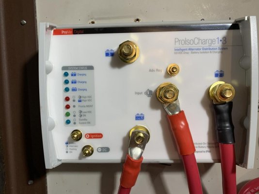
I just checked the manual for the ProlsoCharge 1-3 and it does not talk about jumpers. It does say however that green LED should be on, when the alternator is active. I do not see green now.
Also, if what you are saying is correct, why did it work before and why does it work from my generator? When the generator runs, everything functions. The installation was done by an electrician, so I have never seen the inside of the ProlsoCharge.
Anyway, my regulator replacement for the alternator has arrived today. I will install it tomorrow and test the alternator charge. I’ll report back.

IMG_0840.jpg
 
I just checked the manual for the ProlsoCharge 1-3 and it does not talk about jumpers. It does say however that green LED should be on, when the alternator is active. I do not see green now.
Also, if what you are saying is correct, why did it work before and why does it work from my generator? When the generator runs, everything functions. The installation was done by an electrician, so I have never seen the inside of the ProlsoCharge.
Anyway, my regulator replacement for the alternator has arrived today. I will install it tomorrow and test the alternator charge. I’ll report back.

View attachment 130600

This post from another forum discusses the same situation I ran into with the same solution recommended by ProMariner. The post also mentioned a filter ProMariner sent to me that I had forgotten about. My isolator started working again after that for awhile. I ended up replacing it about a year later after it stopped working again.

https://rinkerboats.vanillacommunit...otes-promariner-proisocharge-battery-isolator

Doing this from memory now, but with the engine running Check the current at the post on the isolator the alternator wire is tied to. If you have current there, then test the two outputs on the isolator. If you have power on the alternator side, but not the output side, it is probably the isolator.

It also should have a wire connection to the ignition circuit and a (-) wire to the negative buss bar on the two smaller connections on the bottom left in your picture. Yours doesn’t and I believe it should. The ignition signal wire tells the isolator to expect a charge from the alternator. I suggest a call to Promariner to ask about the jumper, the filter, and ignition circuit. The electrician probably replaced a diode isolator with this FET isolator and figured it didn’t need the new ignition circuit wire since diode isolator didn’t. I think ProMariner will insist it does.

The generator and Shore Power supplied current does not usually run through the isolator. It runs through an AC breaker to a separate charger or inverter charger and on to the batteries, never running through the isolator. You have one inbound connection in your picture to the isolator which should be from the alternator.

Hope that helps.
 
Last edited:
Here is a manual I found online. Look at page 9 for the wiring diagram.

https://newcontent.westmarine.com/documents/pdfs/OwnersManuals/ELECTRICAL/353134-36044.pdf

Look at page 5 under “General”, the first bullet:

“Provide the required connection from the key switch and the negative DC connection (manufacturers generally use the color purple as the designation for a “key on” lead)”

If you call Promariner, ask about the adv reg post. You may need that if you have or add an external regulator.


I think Helmsman is onto your problem. The negative and ignition wires MUST be connected. The real question is not why your charging stopped working. It's why was it ever working in the first place, and I think the answer is just luck. This appears to be another case of hiring a pro to come mess up your boat, cost you money, so now you can fix it yourself. Moral of the story? Fix it yourself in the first place.


Just a rant tangent.... Over and over again I hear people say "hire a qualified marine electrician". Can anybody show me one of those? I think equally useful advice would be to hire a Unicorn.
 
Ok guys, it is working now.
There is voltage on the volt meter in the PH, green light for the alternator input is on on the isolator, the Victron dc-dc chargers are sending volts to the lithiums, and the crank batteries are full. The way I planned originally.
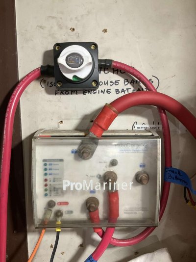
Now the bad part. It was possibly my sloppiness. I installed an on-off switch between the alternator output to the ProMarine isolator input. This is a simple switch and I was not suspecting it. It was ON. Still, it did not connect for whatever reason. After I installed the new regulator onto the alternator, I was confident that it started to charge now. It did not. I was ready to give up and contemplating to buy a new alternator, when I turned on and off this switch and booom, all came alive. Very basic troubleshooting mistake. Turn your switches, even if they show on. I have learned again.
Of course the real test will be out of the dock and underway. I’ll go out in few days, but I feel that it will be ok now.
One interesting observation. The new controller for the generator came with an extra wire inside. There two yellow, two green, two black inside the housing. One red and one black outside for the ground and positive connections. The original controller came with only one yellow wire. The rest was the same. Luckily, the alternator had the second connector for the second yellow wire, so it all connected fine. I am just curious, why this fancy alternator came with a regulator which had only one yellow wire connection, but the alternator had two yellow terminals?
Perhaps I should not care, since it is working now, but I found it strange. Thanks to all about the help on this.
 
A switch on the B+ wire? Id remove it. Can it handle the max output of your alternator?
 
A switch on the B+ wire? Id remove it. Can it handle the max output of your alternator?

X2. Is there a need to break the circuit there?
The switch has already proven unreliable anyway.

Glad it's working, LeoKa. Now you have a spare reg.
 
Last edited:
I suppose I can take it off. It just helped me to use existing battery cables, which were already crimped. If you guys think it is critical, I can replace it with just one wire. See photo.
Similar switches rated way above 100A at Fisheries.IMG_0149.jpg
 
A switch on the B+ wire? Id remove it. Can it handle the max output of your alternator?
X2. Is there a need to break the circuit there?
The switch has already proven unreliable anyway.

Glad it's working, LeoKa. Now you have a spare reg.
Not only is it unnecessary but if used when running it can destroy the alternator. I dont think there us any need if not running so IMO it is a problem waiting to happen?
 
Got it. I will remove it.
 
Back
Top Bottom