Auxiliary Light Panel for Marine Trader

The friendliest place on the web for anyone who enjoys boating.
If you have answers, please help by responding to the unanswered posts.

Mark Myns

Veteran Member
Joined
Aug 31, 2015
Messages
31
Location
USA
Vessel Name
Hoosier Daddy
Vessel Make
38 Marine Trader Sundeck
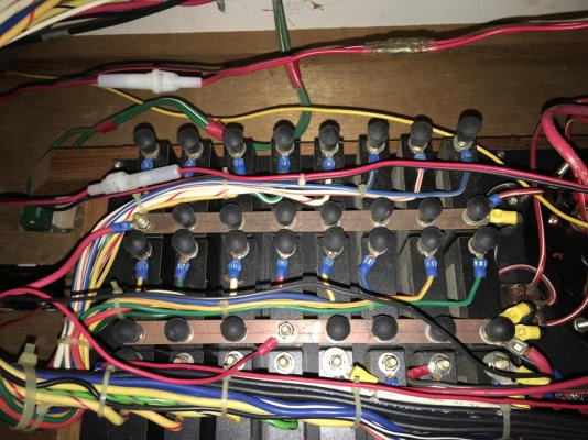
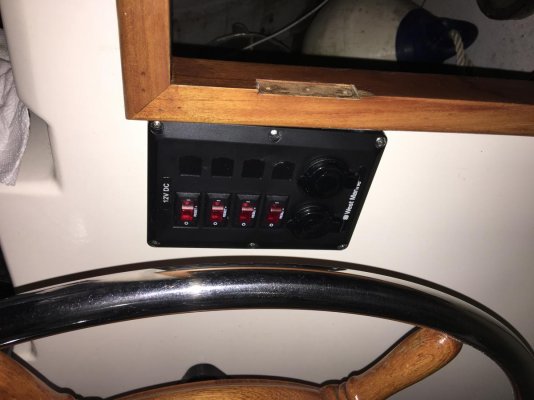
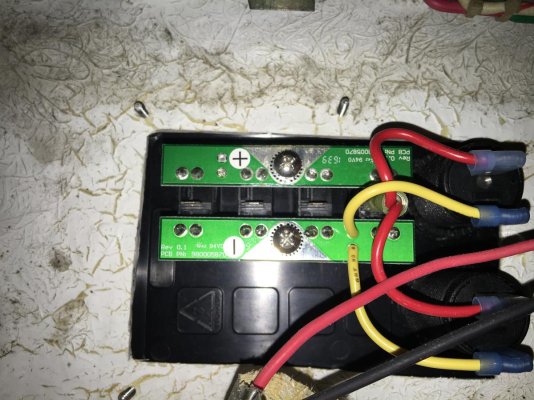
I am putting in an auxiliary panel to control some new lights from my upper helm. I do not want to tap in at the upper helm because all of the electrical up there seems to be tied into the ignition and shuts down when I start the boat or if the key is off I have no power. My thought is to run a new lead from the main panel to the auxiliary panel and power the light off of that. I am going to have my spotlight and two side floods hooked to two of the switches. The third switch I have not decided on at this time, maybe safety floor lighting. All the lights will be LED except the spot light which is remote controlled. Looking at the main panel I am not sure how to connect the wires. I have a couple of breakers that are no longer in use and planned on using one. I am more knowledgeable with AC systems than DC. I assume I would hook the positive to the breaker post and the negative to the bar. I have a 1986 boat so obviously the wiring over the years appear to have been McGivered. I am starting to clean things up. I have included pictures of the backs of both panels and the front of the auxiliary. Any advice would be welcome. Thank you.
 

Attachments

  • Back Main Panel.jpg
    Back Main Panel.jpg
    184.3 KB · Views: 30
  • Front Auxiliary Panel.jpg
    Front Auxiliary Panel.jpg
    97.1 KB · Views: 23
  • Back Auxiliary Panel.jpg
    Back Auxiliary Panel.jpg
    152.2 KB · Views: 24
Your breakers look like they are all connected to a bus bar. This makes it easy, you run a wire from the non bus bar side of the breaker and run it up to your sub panel, this is your power wire. I’d recommend a 30 amp breaker with appropriately sized wire. The ground wire runs from your sub panel to your DC ground bus bar.
 
Bus Bar

I appreciate your help with this but I am still somewhat confused by the system. Is that the negative bus bar that runs along side each set of breakers? I am use to it being completely separate and away from the breakers like on your home breaker panel. I really appreciate your advice. Thank you.
 
I recommend buying a good sturdy DVM. It will save time and last as long as you will.
My Fluke has been with me for at least 25 years. You will always know what is + or -.
If you already have one then ignore that.

It is common to have a positive bus bar that the breakers tap into.
 
Last edited:
I'm not convinced that we are seeing the negative bus bar in the picture. Do you see a bus bar with a bunch of black and/or yellow wires going to it?

If you look at the breakers, one side of the breaker is attached to a bar shared by all breakers. This is the side that gives it power.

The other side of the breaker is where the load is attached. This is where you want to attach your wire. An unused breaker won't have any wire attached to the post at this end.

But, please be careful. In a normal situation, one sizes the wire to the load and then the breaker to the wire. The breaker should be chosen to ensure the wire can't overheat. At the other end of the wire, if there are multiple loads, each should be fused to ensure that each is protected and can't overheat because the supply breaker is sized for the aggregate load, not an individual component.

In your situation, if you are trying to reuse a breaker, you need to check two things: (1) Is it large enough for the load? If not, you'll get nuisance trips. (2) Is the wire large enough for the breaker? If not, the breaker can't do its job of protecting the wire.

Additionally, you need to make sure that each of those switched loads is protected with a reasonable fuse or breaker for the load. It looks like the switches may have some type of breaker built in. But, you need to sanity check it to make sure it is appropriate to the individual load.

If the breaker is too small for the load, you've got no choice but to replace it. If it is too large, you can buy thicker (lower gauge #) wire -- or you can buy the right wire for your need -- and a smaller (lower trip current) breaker.

When sizing the wire and the breaker, consider both the loads you are putting in now -- and the possibility of future loads. It is fine to have thicker wire and a breaker that trips at a higher current than you need -- as long as the individual loads are individually circuit protected properly. In addition, oversizing the wire and branch breaker now mean that you won't end up taking the bus bar apart or running a new wire later.

Hope this helps.
 
It may be easier to start at the battery and run a positive up to the flybridge. It will need to be a good sized wire depending on the distance and power you want available. It will need a fuse or breaker by the batteries. Then run it to your new breaker panel on the bridge. Add a small ground bus bar on the bridge for the negative side. Run an appropriate size cable from the ground bus bar on the bridge to the negative side of the battery or your main ground bus bar. This way you can size it to give you a 3% or 10% voltage drop. I did this on my boat to add a panel for just electronics since the original wire to the flybridge panel was undersized and the voltage was low on the bridge. I ran a #2 or #4, don’t remember which, through a 40 amp breaker to the new Blue Seas 8 position panel. Then I ran the same size black negative from the new ground bus bar to the main ground bus bar in the engine room. Now I have good voltage on my electronics panel and since I took so much of the load off the original electrical panel the voltage on it is good too. And it left the empty breakers on my main panel still empty for expansion in the future.
 

Latest posts

Back
Top Bottom