Electrical question - inverter 'chassis ground'?

The friendliest place on the web for anyone who enjoys boating.
If you have answers, please help by responding to the unanswered posts.
Regarding case grounds for inverters and inverter/chargers:

1. The installation manual from the inverter/charger and inverter manufacturers requires a separate case ground.
2. The American Boat and Yacht Council's relevant standards require a separate case ground.
3. ISO 13297, the relevant marine electrical standard in Europe requires a separate case ground.
4. The guy selling wire at the chandlery tells the OP that a case ground is not required.

You choose...it's your boat.
 
Last edited:
The case ground (which should be no more than one size less than the DC cabling from the batteries) is there in case there is a DC short (or an AC short) but the ground has to also carry the possible large amperage discharge from the batteries to the case.

The most common mistake is that installers use the smaller AC gauge wire to ground the case. That is what my installer wanted to do, until I showed him the many, many admonitions not to, including in the manual, in books on boat electric, forums, and manufacturer sites.

In all my research on this subject, I have never heard of anyone putting a “jumper” from the B- to the case ground. Doing so would potentially flow voltage from the case, through a person touching the case and on to any other metal (or water in the bilge) on to other points. Really bad idea. The counter guy is incorrect and needs to have it explained to him.
 
Last edited:
@Helmsman #32
In all my research on this subject, I have never heard of anyone putting a “jumper” from the B- to the case ground.
Unfortunately, when DIY'ers, inexperienced professionals or professionals that are lazy and don't RTFM, it will happen. I literally removed one of these jumpers this past Thursday from a "professionally installed" Xantrex that I was replacing!
 
@Helmsman #32

Unfortunately, when DIY'ers, inexperienced professionals or professionals that are lazy and don't RTFM, it will happen. I literally removed one of these jumpers this past Thursday from a "professionally installed" Xantrex that I was replacing!

The impetus for me learning marine electrical came about due to an inverter/charger install. Along with this issue, the “best electrician on the lake” ran an undersized wire from the isolator to the inverter batteries for charging (through the 300 amp main fuse for the bank) and didn’t run a B- back to the negative Buss. Glad he didn’t run the negative, because if he had, the charge coming off of the isolator would probably have fried the undersized wire when the batteries were low.

One of the biggest issues facing the marine industry is the lack of qualified electricians, and the lack of new ones in training. A huge opportunity for any young people who want to learn a trade exists in this field. I spoke with a few at the NMEA workshops I attended and they were all planning on branching out and hanging up a shingle.
 
Last edited:
@Helmsman #34:
One of the biggest issues facing the marine industry is the lack of qualified electricians, and the lack of new ones in training. A huge opportunity for any young people who want to learn a trade exists in this field.

True, that! In the Florida Tampa Bay area there is an absolute paucity of truly qualified and experienced (there is a difference!) marine electricians. We are generally booked 6 to 8 weeks out and could work seven days a week if we wanted (we don't!).

The boatyards in this area are begging for technicians but unfortunately the talent pool, for whatever reason, is not low, it is empty.
 
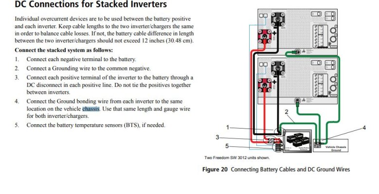
Chassis GND.jpg

follow the wires. The chassis wire goes to a chassis connection point on a metal vehicle or to the DC negative on a boat. You can see a jumper from chassis ground to DC -.

It amazes me that no one can explain the reason why, other than point to ABYC and say because they said so, that you need to run a separate line from chassis to negative connection point. Perhaps this connection point must be within 7 inches like the overcurrent protection?
 
@Soo-Valley
follow the wires. The chassis wire goes to a chassis connection point on a metal vehicle or to the DC negative on a boat. You can see a jumper from chassis ground to DC -.
You are now conflating automotive/RV installations with marine installations. Come on. But be that as it may, note that even in the automotive installation there is a redundant case ground attached to the chassis. Redundant.

It has been carefully explained that the equipment manufactures require a properly sized redundant case ground to the B- bus. This is also reflected in the ABYC and ISO Standards. The technical reasoning has been explained at least three times in slightly different matters. That you seem to want to believe the counter guy at the chandlery is entirely up to you. IYB.
 
one simple question.

Should a boats ground system be connected to DC negative?
 
Yes, but understand the how and where is important too. “ground” is rather a non-descript term leading to confusion.
 
Last edited:
Hey Charlie, That came out of the Xantrex installation. That you and others are unable to explain the reason why the chassis ground and the DC- is connected at the other end of the boat instead of at the inverter is the mystery. It should have an easy explanation instead of beating around the bush. What was the reason ABYC made that a rule?
 
Internal dc neg to chassis bond scenario:

If u loose the DC- feed, and the chassis is grounded with small wire to the AC system, you will melt/flame that green wire. Just as problematic as the DC POS fault to the chassis.

Also, you cant sell the inverter into DC POS grounded boats. All 12 of them. [emoji41]
 
@ofer #40
Since grounds and grounding are so poorly understood; what do you mean by the "...boats ground system..." and I am not wasting your time by being facetious.

The short answer is that all ground, grounding and bonding busses are to be interconnected to the main engine block or preferably to its negative bus. This establishes a 0VDC potential reference for all of the metal on the boat.

There are caveats when the engine manufacture requires that the block must be isolated but those cases are becoming rarer.
 
Hey Charlie, That came out of the Xantrex installation. That you and others are unable to explain the reason why the chassis ground and the DC- is connected at the other end of the boat instead of at the inverter is the mystery. It should have an easy explanation instead of beating around the bush. What was the reason ABYC made that a rule?


The reason is to have a completely redundant return path who's only job in life is to carry fault current. It's the same rational behind the green wire ground in an AC power system, and why you don't just connect the appliance case to the neutral power conductor.
 
Hey Charlie, That came out of the Xantrex installation. That you and others are unable to explain the reason why the chassis ground and the DC- is connected at the other end of the boat instead of at the inverter is the mystery. It should have an easy explanation instead of beating around the bush. What was the reason ABYC made that a rule?

In my opinion, the answer lies partially within the dual electrical nature of the inverter. A short to the case could occur within either the AC or the DC circuit. Either circuit’s short must be able to be carried to ground on a wire capable of bearing the highest amperage that could conceivably travel on that wire.

The idea that it would be ok to have the case short (AC or DC) electrical charge travel back to ground through the B- wire pre-supposes that the B- path never gets interrupted. One purpose of the case ground is to provide a redundant low resistance path until the DC breaker opens.

Remember that the primary inverter DC circuit travels from the battery to the inverter, and then back to the battery. That is what happens on an inverter/ charger install with its own set of batteries. That circuit should never normally touch any part of the metal case. And it does not necessarily travel back to a ground, unless, perhaps a charger or an alternator is attached, which isn’t necessarily the case, at least in an inverter charger.

The DC breaker may not open if the path goes through the case via a fault, then through the B- and then back to the battery. At least until a human creates a new path, unless of course the human has both hands on the case, then the human may just be part of the circuit.

Said another way, if you energize the case by having the B- permanently connected to the metal case, then the case can serve as an alternate path for the normal DC electrical flow. That the normal path is a more likely path for the normal DC current, doesn’t mean that it would always follow that path. It could leave that “circuit” via a human who happens to touch it. The breaker should open, but the damage may be done.
 
@Soo-Valley #42
True and it shows a redundant case ground.

Asked and answered ad nauseum.

What do you think about the holding power of a Fortress anchor in mud with a rope/chain rode?
 
@ofer #40
Since grounds and grounding are so poorly understood; what do you mean by the "...boats ground system..." and I am not wasting your time by being facetious.

The short answer is that all ground, grounding and bonding busses are to be interconnected to the main engine block or preferably to its negative bus. This establishes a 0VDC potential reference for all of the metal on the boat.

There are caveats when the engine manufacture requires that the block must be isolated but those cases are becoming rarer.

As i see it and i am no expert. a boats ground is some metal that have a connection to the surrounding water. i refer to DC ground as the negative on my battery.

if they are connected then the question becomes what different does it make were the wire from the case is connected too as long as its not connected directedly to the negative terminal of the inverter.
 
Helmsman. You are thinking. The case/chassis is normally not energized. With AC ground and DC- bonded if the case becomes energized then either the AC breaker or the DC fuse would open, or would they?
AC is designed to trip breaker if power leaks into the green ground. But DC power into a separate chassis ground wire goes back to the same place as the main DC-, why would the fuse open because current is travelling on a different wire?

If DC- & AC green were not bonded then a chassis wire to green ground would protect a person from touching a hot case without leaking AC into the bonded circuit, into the water.

Back on topic, since everything is bonded why not ground the chassis to the DC- already present as the traveler to ground.
What was the reason ABYC made that a rule?
 
SV stated: Helmsman. You are thinking. The case/chassis is normally not energized. With AC ground and DC- bonded if the case becomes energized then either the AC breaker or the DC fuse would open, or would they?
—————
Helmsman: There are different scenarios depending on the way the inverter is wired.
Perhaps, but not necessarily, though more likely with an AC short feeding the ground attached to either the B- or the redundant ground to the buss bar. Any inherent resistance in the case could trip one or the other.
—————
SV stated: AC is designed to trip breaker if power leaks into the green ground. But DC power into a separate chassis ground wire goes back to the same place as the main DC-, why would the fuse open because current is travelling on a different wire?
—————
Helmsman: It usually isn’t a none or all. The current flowing back to the battery may not equal the current flowing out. That is what is fused. Some of the current may flow through the case to the ground to the engine or buss bar. If, on the other hand, the metal case resistance is low enough, and you have the ground jumpered to the B-, then you might very well have a live case.
—————-
SV stated: If DC- & AC green were not bonded then a chassis wire to green ground would protect a person from touching a hot case without leaking AC into the bonded circuit, into the water.
—————
Helmsman: The AC green wire would never handle the amount of amps flowing through a DC circuit the size an inverter needs to convert to 110. It would just melt and burn. Nor would the bonding system, which is designed to equalize electrical charge between underwater metals. Those wires would melt, too. That is the reason the ground has to be either the same as the DC cables or one smaller size.
—————
SV stated: Back on topic, since everything is bonded why not ground the chassis to the DC- already present as the traveler to ground.
—————
Helmsman: No reason to respond to this again, but….redundancy in case of circuit interruption, or perhaps in the case of a closed inverter/charger to battery circuit, an alternate path to ground if the case is energized, if the DC circuit doesn’t have one.
—————-
SV stated: What was the reason ABYC made that a rule?
—————-
Helmsman: I personally can’t speak for the ABYC. Perhaps a call to them would elicit a response for you. I think they will probably echo the many thoughts provided throughout this discussion, but again, probably best to just pick up the phone and call them.

Sincerely hope this helps, but I am now probably moving into the theory of electricity. The theory of electricity is something I am still a novice with. Though one day I do hope to understand it better.
:)
 
Last edited:
Helmsman. You are thinking. The case/chassis is normally not energized. With AC ground and DC- bonded if the case becomes energized then either the AC breaker or the DC fuse would open, or would they?
AC is designed to trip breaker if power leaks into the green ground.


That's not what a breaker does. It trips if there is an excess of current, regardless of the return path. The ground wire is there to provide a likely/preferred return path vs through somebody touching a case that has become energized via some fault.


But DC power into a separate chassis ground wire goes back to the same place as the main DC-, why would the fuse open because current is travelling on a different wire?


Same as above. A DC breaker (or fuse) will trip on over current. It's blind to the return path.


If DC- & AC green were not bonded then a chassis wire to green ground would protect a person from touching a hot case without leaking AC into the bonded circuit, into the water.


This is really an argument for/against bonding between AC ground and DC negative. This debate has been around about as long as anchors, but the world is aligning on requiring bonding.


Back on topic, since everything is bonded why not ground the chassis to the DC- already present as the traveler to ground.


See post #45. It's to provide a dedicated safety conductor that only carries current in a fault condition. I'm not sure why you aren't hearing or accepting this answer.


What was the reason ABYC made that a rule?


Charlie might know. It was before my time.
 
Last edited:
The chassis does need a ground in addition to the AC safety ground, it's egregious that the sales clerk would have suggested otherwise.

Not only does it need to be bonded, the bonding wire needs to be able to carry full DC fault current, which means it has to be no less than one size smaller than the primary DC positive power cable. Big. This is an ABYC requirement as well.

Details here https://stevedmarineconsulting.com/inverter-installations/
 
Hi everyone - I'm the OP on this thread and want to thank you all for your help and input. I learned a lot (as always) and had several big laughs (as always) especially when we drifted, or were pushed, into anchor wars.

Anyway, it now seems very clear to me why this chassis ground needs to be there, and why it needs to be BIG. It was clearly and logically explained by several posters. And thanks to Charlie for his extreme patience with doubters..

As a follow up - I called the store who gave me the incorrect advice and spoke with my 'usual' guy there. He quickly realized which salesperson I had been speaking to and promised to follow it up. Then he put me on hold to speak with the tech's out back. He returned to say the REAL advice (today) was to DEFINITELY install a chassis ground with THE SAME SIZE WIRE as the DC negative. Which in my case is 4/0.

He said: "I know the regs say you can go one size down, but our tech recommends you use the same full size."

Now that's a turnaround..

and the million$ question...where is that chassis ground will be connected too?
 
and the million$ question...where is that chassis ground will be connected too?

To the engine negative ground or its bus. If you connect to the bus, then make sure the bus to engine ground is at least as large as the case ground cable to the bus.
 
My engines have NEG disconnects, so using engines not great for “ground”. So best to use dc bus NEG. Now the decision is which side of the current shunt.
You can see how folks get confused on this.
 
Fault current needs to return to its source, the battery, so connecting to an engine block isn't really ideal, as that lengthens this path, adds resistance and it can more easily be interrupted. Ideally the chassis ground should be connected to a grounding bus which is connected to the DC negative bus and as others have said the ampacity of all needs to be able to support full fault current, i.e. equiv. to 4/0 in this case.

Also, I prefer to not use the engine as a grounding bus, engines whose blocks are current carrying, i.e. they do not have isolated ground starters and alternators, (they are "grounded", which is different from "grounding") are prohibited from being bonded in any event, as bonding wires should not carry current under normal conditions. If the engine is an isolated ground, then much like an inverter its block needs to be bonded with a cable the same size (or one size smaller) as the positive starter cable, so it can safely carry the highest available fault current. It's even more critical on engines because starter cables are typically not over-current protected.

The risk here is a small wire attached to an engine block, whether or not it is current carrying, can become part of a fault current path, or even a current path for the starter or alternator. I have seen this happen, where a 500 hp. engine was started with a compromised DC negative supply, a #8 bonding wire attached to the block vaporized before my eyes, igniting the wiring harness, and filling the engine compartment with dense white smoke. Keep the engine electrically clean and free of wiring not related to engine applications, IMO.

The attached diagram from ABYC represents this.
 

Attachments

  • DC System.jpg
    DC System.jpg
    119.1 KB · Views: 48
Fault current needs to return to its source, the battery, so connecting to an engine block isn't really ideal, as that lengthens this path, adds resistance and it can more easily be interrupted. Ideally the chassis ground should be connected to a grounding bus which is connected to the DC negative bus and as others have said the ampacity of all needs to be able to support full fault current, i.e. equiv. to 4/0 in this case.

Also, I prefer to not use the engine as a grounding bus, engines whose blocks are current carrying, i.e. they do not have isolated ground starters and alternators, (they are "grounded", which is different from "grounding") are prohibited from being bonded in any event, as bonding wires should not carry current under normal conditions. If the engine is an isolated ground, then much like an inverter its block needs to be bonded with a cable the same size (or one size smaller) as the positive starter cable, so it can safely carry the highest available fault current. It's even more critical on engines because starter cables are typically not over-current protected.

The risk here is a small wire attached to an engine block, whether or not it is current carrying, can become part of a fault current path, or even a current path for the starter or alternator. I have seen this happen, where a 500 hp. engine was started with a compromised DC negative supply, a #8 bonding wire attached to the block vaporized before my eyes, igniting the wiring harness, and filling the engine compartment with dense white smoke. Keep the engine electrically clean and free of wiring not related to engine applications, IMO.

The attached diagram from ABYC represents this.

Thanks Steve. Every time you post I learn a little more. Can you comment on the ground wire between the two engines and what it’s purpose is?
 
Thanks steve,

i thing the question that some of us have is..

If the DC main negative bus and the grounding bus are connected then why it make a difference if the case grounding is attached to the dc bus or the grounding bus.

the windlass wires are a good example
 

Latest posts

Back
Top Bottom