Thanks TT, really appreciate your considerable knowledge and time to respond.
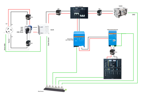
There are no loads connected before the inverter, which has a 50A transfer switch for when shore/generator power is available. I have to manually manage loads while inverting to keep below 2400W continuous.
The neutral wires are still present from both the Iso transformer, and generator, as are the 3 pole switches. I could easily re-connect them if option 1 is a more advantageous wiring approach given the hardware I have.
The inverter is currently wired to internal ground relay in the AT, using the 24V control wires.
I suppose my goal was to use option 2, but you got me wondering if that is ideal with the hardware I have?
I think either option 1 or 2 is fine. I personally prefer Option #2 because I think a common neutral and single point of bonding is easier to keep track of, and less prone to getting messed up down the line. But that's a personal choice.
With the AT, Option 1 will give you an elevated neutral on the AT in pass through mode, and option 2 will give you circulating currents in pass through mode. In both cases, the trick is to minimize them. There is active work going on in ABYC to address this, but it's been slow going. I expect the guidance for maximum neutral voltage lift or circulating currents will be in the 1-2% of the circuit capacity. In my experience, the Victron AT will never come close to meeting that because it's windings are intentionally asymmetric. The only way you can get the numbers down to an acceptable level will be with a symmetric winding AT.
There also is a whole other can or worms around over current protection for these devices. The capacity of the inverter, especially in pass through mode, and even more again if the inverter can boost pass through current, least to a large breaker on the inverter output leading to the loads. But the AT capacity is typically much lower because it's only rated for the max imbalance between L1 & L2, and never needs to carry the full output load of the inverter system. That calls for a breaker that can be 1/2 or even as low as 1/4 the rating of the main output. The catch is that these to overcurrent devices need to somehow be interlocked such that a trip of the AT breaker will in turn trip the main breaker, Otherwise if only the AT breaker trips, you end up with a split phase system with a disconnected neutral, and that is very likely to lead to equipment damage, and very well could cause a fire. In a nutshell, and 120V devices that are connected will see anywhere between 0V and 240V, and that can be disastrous.
Victron's packaging makes this easy because it includes the "main"breaker", and then there is electronic sensing of the AT itself and it remotely trips the breaker if there is a problem. So it's a nice package, except it's asymmetric.
I have solved this on one boat by using an aux contact on the AT breaker to trigger a shut trip on the main breaker. It works well, but is a bit of a tricky and expensive pile of ABB parts to make it work.
Honestly, the best solution is a native split phase inverter, but those are few and far between, I'm afraid.