Inverter Install basics

The friendliest place on the web for anyone who enjoys boating.
If you have answers, please help by responding to the unanswered posts.

BDofMSP

Guru
Joined
Sep 5, 2013
Messages
931
Location
USA
Vessel Name
Gopher Broke
Vessel Make
Silverton 410 Sport Bridge
I’ve been thinking about adding an inverter as a future enhancement. There are a lot of different models, with a range of options, and I get confused about the installation requirements. The “rest of the internet” is not a lot of help – I get a ton of conflicting information and much of it is not marine-based anyway. So I seek to better understand.

Before I even start this, let me say that I’ll definitely work with a qualified marine electrician to do the work, so don’t worry that I’m going to kill myself or burn down the boat. But I like to understand how everything works, and frankly I have gotten contradictory information from “qualified marine electricians”, which confuses me even more.

Background about the boat, it has a single 50 amp 120/240 AC service with no 240 circuits on board. Each line feeds a separate 120 volt half of the panel. There is also a generator that also powers each line, and a sliding interlock to manage the switches and isolate the sources. Very traditional.

I’d like to start with the most simple example with the disclaimer that I’m really trying to avoid rebuilding my entire electrical panel as much as possible. In this simple example we’ll act as though my boat has no generator, and I’m just adding the inverter. Pretend also that I am happy only powering the loads on one half of the panel with the inverter. The other line would remain cold when I’m not on shore power. I’ve attached a diagram of that solution, and I’d appreciate feedback. Essentially it shows me adding the inverter where the Gen currently is wired, but since it’s only 120 it is only powering Line 1 circuits. The manual interlock protects against simultaneously powering with both sources.

In the 2nd figure I extend the solution to match my current situation. I replace the sliding interlock with a rotary selector switch such as a Blue Sea 1488 (120/240V AC Rotary 65A OFF + 3 Sources), also pictured in that figure. This allows me to keep the gen, hence powering both lines offshore if needed, but enabling my simple needs to run off the inverter most of the time. The inverter would be “Shore 2”.

Note: In NEITHER of these situations is the inverter powered by AC with a pass through or a transfer switch. Moreover, this is simply an inverter, not a charger. I’m trying to keep this example simple for now.

So, details of the inverter installation aside (gauge of the wire, chassis ground, etc.) and ignoring perhaps not using the ideal symbols in every case, are both of these solutions safe and compliant with ABYC? Comments appreciated.

Thanks
BD
 

Attachments

  • Inverter.pdf
    229.3 KB · Views: 144
I could tell you how my installation is set up, but I think I can give you something better.

If you go to the Victron site, then go to e.g. Multiplus you will find a tab called downloads. Once you go to downloads you look for system schematics and it will give you a wide array of installation options. They have this for all of their equipment so you can have a good understanding of what you have in mind.

Of course you should be able to exchange Victron for any other brand you wish to buy.
 
You can't go far wrong following MV Sanctuary and the fantastic discussion on that site. You can see his elegant solution here. I followed his plans and everything worked out great!

My old boat was probably wired similarly to yours and I did not have to upgrade my panel. Btw, is there some reason why you don't want to use an inverter/charger? I believe it can actually simplify the operation and the cost benefit of combining the two features is compelling. I went with the Victron Multiplus inverter/charger and am very happy with it.

Note he suggests using the Blue Sea 9093 switch. Wired as suggested above, you simply select "Shore" or "Generator" and you're good to go.
 
The Victron site is one that has added to the confusion a lot. There are countless documents, but many are for RV's, Solar installs / off grid, etc. Also the Multiplus are inverter chargers which I'm not interested in right now. The missing and confusing parts are typically around the selector switch and configuring a shared-source panel. They always reference a transfer switch which I don't have involved here.
 
You can't go far wrong following MV Sanctuary and the fantastic discussion on that site. You can see his elegant solution here. I followed his plans and everything worked out great!

My old boat was probably wired similarly to yours and I did not have to upgrade my panel. Btw, is there some reason why you don't want to use an inverter/charger? I believe it can actually simplify the operation and the cost benefit of combining the two features is compelling. I went with the Victron Multiplus inverter/charger and am very happy with it.

Note he suggests using the Blue Sea 9093 switch. Wired as suggested above, you simply select "Shore" or "Generator" and you're good to go.

A couple reasons why not an inverter/charger. First, they only charge one bank. I still need to charge the other bank. Second, unless my understanding is way off base, the installation (including changing over the existing charger paths, adding another AC circuit to power it, etc.) is far more complicated. Third they are significantly more expensive and I dont' need to the charger function.

The fourth reason is that I really haven't decided. But I do know that what I've outlined here I could add simply and cheaply, assuming it's accurate.

Thanks
BD
 
Free advice on the internet: I believe the schematic you have to the left where you feed one circuit breaker from the inverter and protect it with an interlock, may be problematic, depending on how your neutral and ground wiring is done. I believe most inverters bond the ground and neutral when it is operating and this would be problematic if half of the boat's AC system is bonding the ground while connected to shore power on the other leg of power, I could be wrong. The example to the right would work.

That said, I would advocate for wiring the inverter, with a built-in automatic transfer switch and a subpanel for the circuits that you wish to power with the inverter. Typically, 2 or three circuits, outlets in the galley, maybe one near a lower helm for AC powered electronics and maybe a fridge. You will need a location for this subpanel of course but you won't have to modify your existing AC panel, just be sure it is powered by a circuit of sufficient wire and breaker size one of your two legs, the one with the majority of the circuits that will be switching to the inverter subpanel. I would further suggest that this works best with an inverter/charger so it will maintain the batteries that power the inverter. It really makes it seamless and you don't have to worry about accidentally overloading the inverter with items like a air conditioner or water heater, because it can only power the loads that are on that subpanel.
 

Attachments

  • Inverter.jpg
    Inverter.jpg
    28 KB · Views: 90
Last edited:
Background about the boat, it has a single 50 amp 120/240 AC service with no 240 circuits on board. Each line feeds a separate 120 volt half of the panel. There is also a generator that also powers each line, and a sliding interlock to manage the switches and isolate the sources. Very traditional.


Our previous boat was set up pretty much exactly like yours; same brand, different model, similar size... and I can at least tell you what we did.

First, we found space to slightly increase capacity on one of our battery banks. Started with 3x G29s or some such on each main bank from the factory, and I had already upped that to 3x G31s... so started with 300-Ah capacity on both banks. In the the "inverter-prep" phase, we changed our starboard bank to 4x GC2s, so that brought the bank to 440-Ah capacity. Lifeline GPL-4CTs, AGMs because 1½ of the new batteries had to fit under the saloon-galley stairs, not accessible for routine service.

Then we installed a ProMariner Combi 2000W/60A PSW inverter-charger to service that starboard bank. (Which meant the original 40A charger was free to service only our port bank -- easily selectable at the Ship's Service box -- which meant marginally better/faster charging for the port bank... as when at anchor and wanting to shoot some juice into both banks...)

Back to the starboard bank and inverter/charger. Our tech re-wired connections in the main AC panel so the inverter serviced all of the light AC loads, i.e. outlets including microwave, coffee maker, entertainments center, etc. That was made easiest by some shuffling inside the panel... so all the inverter-serviced loads were on one of the two 125VAC legs.

Non-serviced loads were mostly heavier: aircons, aircon raw water pump, water heater, and range. And eventually, mostly on the other leg. But then we also chose to NOT supply AC via inverter to the original AC/DC fridges... since they were already DC anyway.

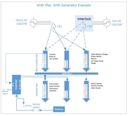
The L1 side of our panels finally looked like this:
Inverter-serviced -- Galley OUtlets, FWD outlets, Salon Outlets, Microwave, Exterior Outlets, Salon Stereo
Not inverter-serviced -- FWD A/C, Refrig 1.

L2 was:
Not inverter-serviced -- Converter, Water Heater, Mid A/C, Air Pump (AC raw water pump), Range, Refrig 2.

The automatic transfer switch within the inverter-charger took care of all the switching.

At least one and maybe more other owners chose to add a while new battery bank to feed an inverter, and the factory sent me some info on how they had done it for somebody too. With the same basic wirig construct at the panel. Both of those located the new battery bank in the lazarette... but I didn't choose to do that. Seemed to work OK for them, though.

Were it today, I might chose a Victron MultiPlus for that, partly because of even higher charge rates available. In fact, we did choose a MultiPlus on this current boat, partly because of that too... but also partly 'cause wwe're now on a 24V boat...)

-Chris
 
Last edited:
First, we found space to slightly increase capacity on one of our battery banks. Started with 3x G29s or some such on each main bank from the factory, and I had already upped that to 3x G31s... so started with 300-Ah capacity on both banks. In the the "inverter-prep" phase, we changed our starboard bank to 4x GC2s, so that brought the bank to 440-Ah capacity. Lifeline GPL-4CTs, AGMs because 1½ of the new batteries had to fit under the saloon-galley stairs, not accessible for routine service.

We just added capacity when we replaced both our banks this year. So we now have 440 Ah per side too, but all FLA in the engine room, and they share start and house duty. Hopefully we won't be replacing them for 6 or 7 years.

Back to the starboard bank and inverter/charger. Our tech re-wired connections in the main AC panel so the inverter serviced all of the light AC loads, i.e. outlets including microwave, coffee maker, entertainments center, etc. That was made easiest by some shuffling inside the panel... so all the inverter-serviced loads were on one of the two 125VAC legs.

Exactly my plan, and why I'm happy to have one the legs "cold" when on the inverter, but hot when on gen.

The L1 side of our panels finally looked like this:
Inverter-serviced -- Galley OUtlets, FWD outlets, Salon Outlets, Microwave, Exterior Outlets, Salon Stereo
Not inverter-serviced -- FWD A/C, Refrig 1.

Exactly my layout but this opens a question. You have "not inverter-serviced" outlets on that leg. Doesn't the source just power the entire buss (sorry if that's the wrong term) for that leg? How are individual circuits "not serviced" if they are on that leg?

Your experience confirms that I'm on the right track, but all the feedback has been for chargers and transfer switches. I'm still hoping for input on the simpler approach.
 
Free advice on the internet: I believe the schematic you have to the left where you feed one circuit breaker from the inverter and protect it with an interlock, may be problematic, depending on how your neutral and ground wiring is done. I believe most inverters bond the ground and neutral when it is operating and this would be problematic if half of the boat's AC system is bonding the ground while connected to shore power on the other leg of power, I could be wrong. The example to the right would work.

Thanks for this information. I'll have to research this more!

That said, I would advocate for wiring the inverter, with a built-in automatic transfer switch and a subpanel for the circuits that you wish to power with the inverter. Typically, 2 or three circuits, outlets in the galley, maybe one near a lower helm for AC powered electronics and maybe a fridge. You will need a location for this subpanel of course but you won't have to modify your existing AC panel, just be sure it is powered by a circuit of sufficient wire and breaker size one of your two legs, the one with the majority of the circuits that will be switching to the inverter subpanel. I would further suggest that this works best with an inverter/charger so it will maintain the batteries that power the inverter. It really makes it seamless and you don't have to worry about accidentally overloading the inverter with items like a air conditioner or water heater, because it can only power the loads that are on that subpanel.

I was SO hoping that I wouldn't have to get to the transfer switch / subpanel conversation yet, but it seems to be unavoidable. I'm not really sure how adding a subpanel doesn't require modifying my existing panel. I don't have room in the panel itself for another one, and even if I did, don't I have to move the circuits to the new panel? And if I move ALL of them, how is it different than just using the leg I had? I feel like I'm missing something.

I am getting good feedback here and I really appreciate it. It probably says more about my linear thinking than anything, but I'd really like to understand if my proposed approach (if not OPTIMAL) is technically accurate and acceptable. Then I can go on to consider other options.

Thanks
BD
 
Free advice on the internet: I believe the schematic you have to the left where you feed one circuit breaker from the inverter and protect it with an interlock, may be problematic, depending on how your neutral and ground wiring is done. I believe most inverters bond the ground and neutral when it is operating and this would be problematic if half of the boat's AC system is bonding the ground while connected to shore power on the other leg of power, I could be wrong. The example to the right would work.

One Inverter that I've considered is the Phoenix Inverter Smart 12/3000. For this model they say "The AC output is not isolated from the DC input. The AC output Neutral is connected to chassis/ground. If the installation requires
a floating neutral, the neutral to ground link needs to be removed." I think this is what you're talking about?

If so, they also say "Ground wire “G“ connects the output neutral to ground. It must be re-positioned to a ‘dummy’ terminal if a floating output is
required."

Would that mitigate this concern?

Thanks!
BD
 
I prefer the option on the right. This makes wiring easy with less chance of error. The switch should have 4 terminals, L1,L2,N and G. Ground and neutral are combined at the inverter and at the generator. With all lines being broken at the switch there is no chance for getting things wrong even if you were on shore power with \the generator running.

It is not How I would do things but base on the requirements you stated it works and will work well.

If you are a heavy inverter user with multiple days on the hook I wouldn’t recommend this set up. If you motor long days and spend short nights on hook then this system will do just fine.

One area that people get wrong is the cost of voltage drop while charging batteries. This is why it is so important not to under size wire between batteries and the charger. It is also why inverter chargers cost more, they deliver a tremendous amount of true amps in charging vs most stand alone chargers.
 
The fourth reason is that I really haven't decided. But I do know that what I've outlined here I could add simply and cheaply, assuming it's accurate.

I think you need to identify what purpose the inverter serves. On my last boat an inverter served the AC refrigerator and two AC outlets. It had a passthrough switch built in on the A/C side. That's pretty simple.

Even simpler is an inverter that you plug a couple of extension cords into.

The modern inverter/chargers are great. If you're going to get into panel and wiring changes I'd push you in that direction. Lots of useful features for load sharing, etc.
 
One issue with your set up, water heater. You could move all heat type sources to L2 to solve this issue or you could just manually trip the breaker on any heat sources. This however could lead to issues if you forget.
 
I prefer the option on the right. This makes wiring easy with less chance of error. The switch should have 4 terminals, L1,L2,N and G. Ground and neutral are combined at the inverter and at the generator. With all lines being broken at the switch there is no chance for getting things wrong even if you were on shore power with \the generator running.

Thanks! The one on the left was basically an exercise in simplicity to help me think through it. The one on the right is how I would actually do it, and your assessment is very much appreciated.

If you are a heavy inverter user with multiple days on the hook I wouldn’t recommend this set up. If you motor long days and spend short nights on hook then this system will do just fine.

We don't have an inverter now, so I can't say I'm a heavy user, but I don't expect to be. Jeff F asked essentially the same question so I'll outline it here.

On 80% of weekends between May and October, we leave the dock either Friday night or Saturday morning, and return Sunday night or Monday morning. During those days I use about 4-6% of each bank's capacity per 12 hour period (because no inverter). In the morning we run the gen for a few minutes to make coffee, a few more to make toast or microwave a burrito, and that's it. Batteries are usually back to 100%. In the evening we run the gen to microwave a veggie or a rice dish, and that's about it. Batteries are usually back to 100%.

20% of weekends we're on longer cruises, but other than when we're in Isle Royale, we cruise distances every day, and end up at a marina half the time. When we're at Isle Royale, it's the same as above, just for longer. But batteries are fully charged each day. And we're doing long cruises every 3 or 4 days.

The refrigerator is 12/120 and works just fine for us on 12 volt. I see no reason to add it to the inverter. Air conditioning and fans are not a thing up here in the northland, and for the 80% we're happy with a swim every day - we don't use the shower. Cruising heats the water for dishes, or worst case we can microwave some. The beer fridge is 12/120 and is already accommodated in my daily usage. We do have an icemaker on the flybridge - we don't care about it but when we have guests I'd run it occasionally to make some for cocktails. Once made it lasts pretty long.

So the use of the inverter (currently the gen) is for those minutes to make coffee and burritos, heat up sides for dinner, and maybe a batch of ice. Half the time I'm underway anyway when it's happening. It's very short, very intentional, which is why I'm not (right now) concerned about elegance or simplicity. We already flip the switch over to run the gen - switching to the inverter isn't any harder.

6-8 or so years from now we'll be doing much more serious cruises but that's the life of this battery bank. By then I can do lithium (or whatever is happening then) and a whole new system. Right now I can do this whole thing (if I chose to) with a Renogy 12/3000 and the rotary switch for way less than a boat buck (I have a bunch of 3/0 and 4/0 cable and terminals and the tools to make them), and pretty simple labor for the electrician. Wiring a 2nd charger, rewiring a subpanel and setting up for an automatic transfer is appealing, but something that can happen with the next round. In the meantime I can make coffee and toast while I'm underway, and ice at 3:00 to prep for happy hour, with no gen.

Glad to hear that there are no deal breakers so far. I very much appreciate all of the input.

BD
 
Having said all of that, I have always intended to continue this thread with further questions about HOW to wire the inverter / charger to accomplish my goals should I choose to go that route. I'm very aware of the appeal, and I've chartered several boats set up that way. I've always been a bit taken back by the seeming complexity of the install, but fully acknowledge that I may be overreacting and just need some education. Like I said above, I like to fully understand the basic option before confusing myself further with additional complexity. I feel like I'm catching up now.

I'll produce another figure tomorrow outlining my understanding of how I'd approach that situation. It's not immediately coming to mind, but diagramming always helps me. For sure it will be wrong, but there are great minds here.

Thanks!
BD
 
I maybe should have outlined our use case, but it turns out maybe much like yours that you described in a subsequent post.

We would seldom anchor out for more than 2 weeks at a time, and usually NOT in July/August when usually AC is required overnight around here... 'cause I don't like the genset noise overnight.

Pre-inverter, we ran the genset for a couple hours in the morning to make coffee and then breakfast (all-electric galley)... while charging batteries and heating water. Ditto a couple hours again in late afternoon or early evening while we make dinner. I didn't mind that, but wanted to be able to make that first pot of coffee, and Happy Hour hors d'oeuvres later, quietly.

Post-inverter, quiet coffee, quiet hors d'oeuvres, and we only needed to run the generator for about an hour in morning and evening to power the cooktop (and heat water and charge batteries and make ice). Having two chargers meant a resulting higher charge rate for each of the two banks... so cramming some amps back into the batteries was just a little faster.

E Voila!


Exactly my layout but this opens a question. You have "not inverter-serviced" outlets on that leg. Doesn't the source just power the entire buss (sorry if that's the wrong term) for that leg? How are individual circuits "not serviced" if they are on that leg?

Your experience confirms that I'm on the right track, but all the feedback has been for chargers and transfer switches. I'm still hoping for input on the simpler approach.

The tech called it a "split buss" approach. He literally cut the L1 buss bar into two pieces, so the top part (inverter serviced) wasn't connected to the bottom part (not serviced). And then he made it so shore power and genset power serviced both parts of that "split buss" -- as well as the L2 buss bar.

The internal transfer switch on the ProMariner inverter/charger handled everything. (Our current Victron inverter-charger works the same way.) It automatically recognized shorepower or genset power, and when neither was present it automatically began inverting. Look Ma! No Hands!

So... were it me, I think I'd shop on the ProMariner Combi if I had a 12V battery bank source and thought I could live with 2000W PSW... or on a Victron MultiPlus 3000W unit if I needed different battery source voltage (ours now is 24V) or if I thought I'd need more capacity (we now have AC-only fridge and freezer). The extra cost for the charger function has been minimal in both cases, it improves our quick-charge capability, and simplified both of our installations. And my brand/model preference is partly based on our experience, and partly based on reading.

-Chris
 
Last edited:
I just installed two Victron Multiplu 2 300o watt inverter/chargers in two different boats. Could not have been easier.


1. Find the two AWG 6 wires (L1 and L2) that feed the two busses on the two strips of 120V circuit breakers from your main/generator lockout switch. They are incredibly easy to find inside your AC breaker panel


2. Disconnect the L1 wire from the breaker bus bar and connect it to the L1 input of ACIN on the inverter with AWG 6 wire.


3. Disconnect the L2 wire from the breaker bus bar and connect it to the L2 input of ACIN on the inverter with AWG 6 wire.


4. Connect the L1 of the ACOUT1 of the inverter back to the bus bar from step 2


5. Connect the L2 of the ACOUT1 of the inverter back to the bus bar from step 3.


6. Find the green ground wire from the 50AMP shore power in. Disconnect it from the ground bus inside the breaker panel and connect it to the ACIN ground on the inverter.


7. Connect the inverter ACOUT1 ground to the bus bar from step 6.


8. Find the white neutral wire from the 50AMP shore power in. Disconnected it from the neutral bus in the breaker panel and connect it to the ACIN neutral on the inverter.


9. Connect the inverter ACOUT1 neutral to the bus bar from step 8.


10. Connect the inverter chassis ground (different than the AC grounds) to the boat bonding system.


11. Connect the inverter DC to the house batteries with appropriately sized wires and fuse. I used 4/0 and a 350 amp fuse.


12. If there's a second bank that needs charging, install an ACR.


The inverter will automatically switch on when shore power or genset power is not providing 240V or 120V to the boat. The inverter will automatically switch off and start charging batteries when shore power or the genset is providing 120V or 240V. You will need to manage your loads to prevent overloading the inverter. The inverter powers L1 and L2 with the same phase, so it is impossible for the inverter to power anything that runs on 240V, though that won't matter to you.
 
One Inverter that I've considered is the Phoenix Inverter Smart 12/3000. For this model they say "The AC output is not isolated from the DC input. The AC output Neutral is connected to chassis/ground. If the installation requires
a floating neutral, the neutral to ground link needs to be removed." I think this is what you're talking about?

If so, they also say "Ground wire “G“ connects the output neutral to ground. It must be re-positioned to a ‘dummy’ terminal if a floating output is
required."

Would that mitigate this concern?

Thanks!
BD

Yes, this would mitigate the concern of tripping a ground fault protected shore power supply. It sounds like it leaves the devices without any grounding, which in my opinion is not the end of the world, small 120V devices did not have grounded chassis for decades and somehow most of the world managed to survive.

On the topic of a subpanel versus a split bus approach of powering selected 120V circuits, a split bus would accomplish the same benefits of a sub-panel and yield a cleaner and more seamless install. Personally, I believe a little more expertise is required in the install to make sure the split bus configured and wired properly but it isn't rocket science. I found the subpanel approach to be easier as a DIY install and I didn't have to run as much wiring, but the configuration of your boat will dictate a lot of this.

Finding a good spot for the inverter can be a challenge, you want to be relatively close to the battery bank, close to the AC panel and in a well ventilated and dry space. This calls for pretty valuable real estate in terms of an equipment install. I see some installed in engine rooms which does not seem to be inline with the inverter manufacturer specifications.
 
Finding a good spot for the inverter can be a challenge, you want to be relatively close to the battery bank, close to the AC panel and in a well ventilated and dry space. This calls for pretty valuable real estate in terms of an equipment install. I see some installed in engine rooms which does not seem to be inline with the inverter manufacturer specifications.


Ah. Good point I forgot to mention.

Our first installation (described above) was delayed several years while I "thought about it" and much of that was how to get the inverter/charger close enough to the servicing battery bank... ideally not in the hot engine room... and close enough to the AC panel.

It turned out I was eventually able to figure out we had almost enough room to park a '57 Chevy behind the interior bulkhead behind our saloon couch (in between that bulkhead and the inside of the hull)... and that location was almost directly above the battery bank I proposed to use. (There was a self-contained AC in the same space and that caused me a bit of worry at first, but we were able to build up a small platform for the inverter/charger, in case we had a condensate overflow or worse, in case a raw water hosed popped off the AC.)

And then it also turned out pulling the AC wires connecting inverter/charger to AC panel wasn't really all that difficult, even though it was from one side of the boat to the other.

-Chris
 
I just installed two Victron Multiplu 2 300o watt inverter/chargers in two different boats. Could not have been easier.


1. Find the two AWG 6 wires (L1 and L2) that feed the two busses on the two strips of 120V circuit breakers from your main/generator lockout switch. They are incredibly easy to find inside your AC breaker panel


2. Disconnect the L1 wire from the breaker bus bar and connect it to the L1 input of ACIN on the inverter with AWG 6 wire.


3. Disconnect the L2 wire from the breaker bus bar and connect it to the L2 input of ACIN on the inverter with AWG 6 wire.


4. Connect the L1 of the ACOUT1 of the inverter back to the bus bar from step 2


5. Connect the L2 of the ACOUT1 of the inverter back to the bus bar from step 3.


6. Find the green ground wire from the 50AMP shore power in. Disconnect it from the ground bus inside the breaker panel and connect it to the ACIN ground on the inverter.


7. Connect the inverter ACOUT1 ground to the bus bar from step 6.


8. Find the white neutral wire from the 50AMP shore power in. Disconnected it from the neutral bus in the breaker panel and connect it to the ACIN neutral on the inverter.


9. Connect the inverter ACOUT1 neutral to the bus bar from step 8.


10. Connect the inverter chassis ground (different than the AC grounds) to the boat bonding system.


11. Connect the inverter DC to the house batteries with appropriately sized wires and fuse. I used 4/0 and a 350 amp fuse.


12. If there's a second bank that needs charging, install an ACR.


The inverter will automatically switch on when shore power or genset power is not providing 240V or 120V to the boat. The inverter will automatically switch off and start charging batteries when shore power or the genset is providing 120V or 240V. You will need to manage your loads to prevent overloading the inverter. The inverter powers L1 and L2 with the same phase, so it is impossible for the inverter to power anything that runs on 240V, though that won't matter to you.

Sorry I replied to the wrong reply. GDavid's message was helpful but THIS posting helped me ENORMOUSLY. Thank you! I'm working on my new diagram.

A couple things. I didn't realize that I would be removing the shore power connection completely from the panel. It now only goes to the inverter, period. That is a big change (both in understanding and in wiring). I also didn't understand how you could power both legs off of the inverter because the models that I’ve been looking at only have one output. For that matter they only had one INPUT too, as they were intended to be much more limited in their functionality and scope.

It also wasn’t clear to me how the generator integrated into the auto transfer solution, and honestly now I’m even more in the dark about that. In my diagram I still have the generator connected to the panel via the interlock, which I ASSUMED that the inverter is also connected to. Looking into the MultiPlus II 2X model, it’s not clear to me. The description makes me believe that the Gen is also connected directly to the Inverter, and that it automagically makes itself one single source, and there is no interlock needed on the main panel at all anymore. Simply the inverter attaching (I assume) to a single main 3 pole breaker. Is that correct? If so, how does the inverter protect itself against getting generator power when it already has Shore AC?

I also see that there is an additional pure pass through output for everything that you don’t want inverter powered (water heater, AC, etc.). If so I assume that I have to create split bus arrangements on each leg.

Regarding location, which Chris pointed out for me, I have what I thought was a good location. The batteries are at the back of the engine room and there is a bulkhead behind them. On the other side of that wall is the lazerette and there is a nice open space on that wall for an inverter. Cool and dry in there, and close to the batteries. It is NOT however close to the AC panel. That is 2/3rds the length of the boat forward of the inverter. I’ve read that I don’t need to be very concerned about the AC voltage drop, just the DC, but now I’m wondering about that.

So I guess my new questions are around how does the gen tie in, whether I still keep the interlock, and whether close proximity to the AC panel is really that important.

Thanks much!
BD
 
May have missed it but an inverter is not a new supply line in like Gen or shore.
From the main electric panel you need a dedicated breaker to feed the inverter (I use 30A), you could use 50A.
Then you reassign on board items to the inverter output (load) line. You have to create an inverter neutral buss bar separate from other neutral buss bar. so when inverter takes over (invert) it has a closed system for just the loads through the inverter. All other loads will not work unless Gen or shore power is on.
What you are doing is feeding all systems from shore/Gen OR just Invereter loads from inverter. The line passes through the inverter from Gen/shore line.

BTW, Your selector switch suggests you use line 1 or 2 separately but not together

Well put !
 
I would go with a charger/inverter. As someone else, there is no need for a transfer switch.

When we leave the dock and if I need AC power for a few minutes. I hit one button and the inverter turns on and feed all the outlets in the boat! But not high amps things, like the hot water heater. So now I can make coffee, run the microwave and anything else that I can plug in. Just too easy to use.

The only thing is, these loads must go though the inverter/charge. Not a big deal to rewire these load to the inverter and the inverter to shore power.
 
I also see that there is an additional pure pass through output for everything that you don’t want inverter powered (water heater, AC, etc.). If so I assume that I have to create split bus arrangements on each leg.

Regarding location, which Chris pointed out for me, I have what I thought was a good location. ... It is NOT however close to the AC panel. That is 2/3rds the length of the boat forward of the inverter. I’ve read that I don’t need to be very concerned about the AC voltage drop, just the DC, but now I’m wondering about that.

So I guess my new questions are around how does the gen tie in, whether I still keep the interlock, and whether close proximity to the AC panel is really that important.


We only had to split one buss bar, but that was after some initial shuffling of some of the original breaker-to-Leg assignments... and after moving some of the individual breakers up or down on the L1 bar (so one segment of the split had what we wanted to service with the inverter, and the other segment of the split didn't).

AC voltage drop turned out to be not an issue, in our case, and our tech said the same thing about it: no worries.

Ease of cable run might be the more difficult part, but generally if there's wiring in the AC panel (there is) then there's usually a way to pull new wires to it, too.

As Steve said, neither shorepower nor genset power connects directly to the inverter-charger.

Instead, a new circuit (with it's own breaker) from your AC panel feeds the inverter-charger. And then in an installation like ours, the I-C feeds AC back to the panel on demand. The I-C's internal automatic transfer switch handles all of the handshake.

I didn't mention it earlier, but the ProMariner Combi and the Victro MultiPlus both have options for monitoring and at least some degree of external control. I think both are just connected with simple telephone wire, RJ-11 jack or some such. Very useful. You'll want to identify a place to install thing like those, too.

-Chris
 
Last edited:
BTW, Your selector switch suggests you use line 1 or 2 separately but not together

If you look closely at his diagram, it is a 240V blue seas selector switch so it makes and breaks both legs at the same time, they aren't tied to each other but they are on the same rotary assembly, it has additional contacts built in.
 
OK, after delay and travel I'm back on the boat and able to return to this. So one thing is very clear - I need to pay closer attention when I read. Man...

I read "Disconnect the L1 wire from the breaker bus bar and connect it to the L1 input of ACIN on the inverter with AWG 6 wire" and I interpreted it as disconnecting the shore power from the switch, and running it back to the inverter. Obviously wrong. So NOW I see that the exact situation that I outlined in my diagram (the interlock or the rotary switch) are still in play exactly the same way. Gdavid correctly pointed out that those labels on the switch are for folks who have two separate shore power connections and are selecting between them. In my case, "Shore 2" is the inverter (and I'd label it as such). Gen is still gen.

So powering the inverter AC from one breaker on the AC panel makes some sense, but it bends my brain to figure out which leg that has to be on. I keep having an image of a snake eating itself as I'm powering the inverter that is powering the leg that powers the inverter...

It must need to be on the non-inverter leg. Currently the battery charger IS on the leg that would be run by the inverter, so I guess that would change. And of course I still need to keep that charger too because the inverter is only charging one bank, so I need to find another circuit on that bus to use.

So now I need to get my diagram broken down in much more detail as to which exact circuits will be on which LEG, and on which half of that leg (inverted or not). I'll work on that Monday because now in a few hours I'm going to go use the boat - without an inverter.

Thanks for bringing me around on this and not pointing out my obvious errors harshly.

BD
 
I have a Magnum inverter/charger. I think there manual on wiring broke it down in simple terms.

Try downloading one of there manuals. Basically, line in (shore power) line put to feed the loads. Than 12v in feeding the inverter.

Shore power "on" batteries are being charged and shore power passes though the inverter feeding the loads. No shore power, turn the inverter on and 120v go to the loads being powered from the batteries.

But you must do the math between battery bank capacity, loads and run times.
 
Last edited:
Corrections Made

Back from yet another wonderful weekend enjoying the boat (without an inverter). One thing became clear to me over the past two weekends - the role of the icemaker. My wife and I aren't big cocktail drinkers. We prefer wine. As such we never miss the (AC-only) icemaker when we're out. But our guests the past two weekends both were cocktail drinkers and we ended up running the gen longer on the 2nd day to refresh our stock of ice. Certainly not common and I'm not going to buy an inverter just for that purpose, but it would have been nice to have that option.

So I have corrected my diagram (attached) which I now believe to be the correct representation of the inverter/charger w auto transfer approach. As Chris mentioned, I probably wouldn't HAVE to split both lines but I probably would. I welcome any corrections to the new version.

I'm now starting to focus on the comparison of the approaches to help me decide on advantages and disadvantages based on my use cases.

Thanks!
BD
 

Attachments

  • Inverter w transfer.pdf
    219.6 KB · Views: 39
I suspect that the inverter would be 120 output, not 120/240, so your schematic maybe should look like this.

Another suggestion - have at least some outlets on the non-inverter side. When unattended and on shore power you may have some loads that you do not want the battery to feed in case of loss of shore power.
 

Attachments

  • Iverter diag01.JPG
    Iverter diag01.JPG
    63.6 KB · Views: 46
I suspect that the inverter would be 120 output, not 120/240, so your schematic maybe should look like this.

Another suggestion - have at least some outlets on the non-inverter side. When unattended and on shore power you may have some loads that you do not want the battery to feed in case of loss of shore power.

Thanks for the feedback. I based that diagram on the MultiPlus-II 2x 120V manual (as it was suggested here earlier). That model shows "Load connection AC out1 - From left to right: N (neutral), L2 (phase 2), PE (earth/ground), L1 (phase 1)". So I think it's accurate if I use that model. It also has an AC Out2 which is simply passthrough (not inverted) but short of a separate sub-panel I struggled to figure out how or why to use that in the setup I diagrammed.

I'll think more about the comment about the outlets. On my boat the only outlets that would have an active load on them (if shore was removed) would be the salon stereo, which would only be in standby, and the toothbrush charger in the head (but that would be charged). We don't leave any other AC items on when we're away (the refrigerator is AC/DC). But thinking about it, we don't need the salon stereo on the inverter at all - we use the flybridge stereo when anchored. I'll move that to the other side.

Thanks,
BD
 
Back
Top Bottom