A friend just read my prior post and tells me it was entirely unhelpful for the intended audience, including him, and that I need to explain three things or it's all just more useless noise taking up air time to most folks, so let me try to be more helpful:
1) What are the red things and why am I calling them phases?
2) What is a nonlinear load?
3) What is a harmonic and why is it bad.
This is serious thread drift. But, let me add this as a caption to my prior figures and then leave it to the power engineers, perhaps in a new thread. I just don't want anyone to feel like I was trying to be unhelpful or feel left behind if it is something they happen to care about (most probably won't...)
1) Most of us are familiar with the shape of a sine wave and know that AC is called AC because the current alternates up and down with this wave form and that in the US this happens at a frequency of 60x/second or 60Hz. So the wave form repeats itself ever 1/60th of a second. If we pick some starting point on the repeating waveform, phase is just a measure of how far the wave the wave is right now from that starting point vs how far it has to go to get back to that part of the shape again. If we take the same shape and start the wave at different times the phase difference is just how far they are apart w.r.t one wave being in the same position as another is now. Degrees are one way of measuring this distance when we are comparing waves of the same frequency.
--
https://matterofmath.com/wp-content/uploads/2021/03/Phase-shift-sine-wave.jpg
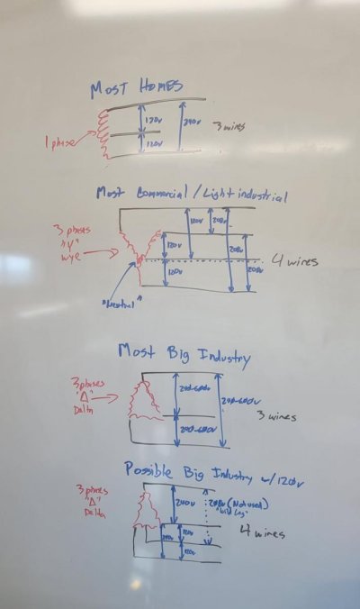
With three phase power three 60Hz sine waves are generated, each 360 degrees/3 = 120 degrees apart. The red squiggles are
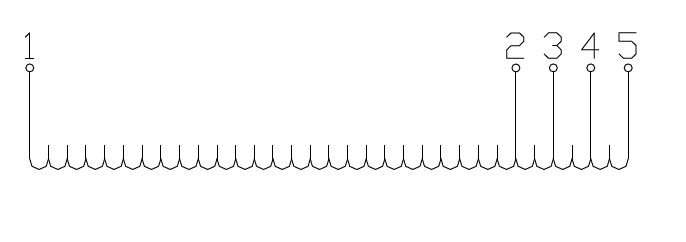
The secondary windings of transformers where each of these electrical waveforms enter the system. The primary windings are tied to the generator that produces them or voltages stepped up or stepped down from them by transformers, depending upon where one looks.
Because alternating current moves charge, it produces a changing magnetic field called Flux. This changing magnetic field can induce a current flow in a nearby wire. The voltage associated with that current is related to the ratio of the number of coils on the primary vs secondary windings. The secondary coil loads the primary coil generating an impedence to current flow there, so nothing is free. The load in theb2ndary is felt by the primary. If the voltage is stepped.up and higher on the 2ndary (more windings) the primary will experience a greater current flow so the work is the same (actually more with inefficiencies). Beyond this a core is used to shape the magnetism and this core isn't passive and can be impacted by the properties of the supply and load.
3 phase turns out to be more efficient for distribution that other numbers of phases with respect to the wire needed to carry the load, etc. Thats why it is used.
So, the red squiggles are the 2ndary windings of transformers, each providing a 60 Hz waveform 120 degrees apart.
2) Many of us may be familiar with Ohm's law, i.e. voltage is equal to current over resistence, i.e. i=v/r. Note that voltage is proportiomal to current, so the two are in phase with each other, i.e they move up and down together. This is true only for simple resistive loads, e.g. incandescent lights, old fashioned electric cook tops, resistive heaters.
Nonlinear loads, at least as I was using the term, are loads where Ohms law is not enough to model the situation because it doesn't account for time. The easier example of this is probably a capacitor. It charges up over time and then can discharge over time. When it is charging it is drawing a lot of current. When it is discharging it is supplying current and supporting voltage. In this way it tries to change the waveform it is being fed. The impact of this can be modeled as a phase shift. Inductive loads do the same thing, except they store energy magneticly vs electrostaticly. Another way if viewing these loads is that they are loads where the voltage and current curves aren't in sync.
It is important to understand that these active properties of components don't just impact the load and things downstream from them, they impact the supply, itself. It is all part of the same circuit. As a result, they can impact the way the supply performs and the electricity other devices see. Basically, all of these active components have an effect that has to be combined with the properties of to understand the behavior of the circuit.
Any single consumer device probably cant make much of a difference. But, add them all up and they sure can. What was once mostly an industrial challenge is now ubiquitous. Think of all the devices in your home with power supplies that use capacitors for filtering or efficiency, especially bigger ones like switching supplies on computers, as well as CFL lights, and hidden ones such as those for LED lighting and the computers embedded in all sorts of devices.
3) The difference between the ideal waveform that one wants to supply and what one actually ends up with is called noise. There are a lot of ways to describe or model it. But, it is really helpful to do that in a way that is easily modeled and analyzed mathematically or, at the least, in a way for which there are good, well understood mathematical tools.
As it turns out if we think of the noise in terms of the impact it has at different frequencies instead of at different times there are much better ways to analyze it. In particular, we can do this by looking at the noise in terms of its impact at multiples of the fundamental frequency, in this example 60Hz.
We call the fundamental frequency the 1st harmonic, (1x itself); double it, e.g. 120Hz, the 2nd harmonic; triple it the third harmonic, etc.
When it comes to these harmonics they can do strange things. Even harmonics tend to cancel out. Odd harmonics tend to add up. Triplen harmonics, the set of odd harmonics which I mentioned earlier, tend to be produced by 120v single phase loads. In particular, they can mess up the wave form making the use of the electricity less efficient for some devices and adding noise to the workings of others. They can also change the way the electricity flows through the cross section of wires requiring thicker wires, change the way the magnetic field forms and communicates energy at transformers, and change the flow through transformer networks, concentrating or canceling themselves.
Noise like this is very hard to control, except at the original source. It can't, for example, be filtered by capacitors. It's effects are just too complex. And, even at the source, beyond taking the big chunks out, it can get expensive and complex fast.
Through some true sorcery power EEs can design an utilize specialized transformers that phase shift waveforms so that these harmonics are combined inverted and significantly cancel themselves.out, e.g. zigzag transformers. And, their bag of spells and magic doesnt end there. Not nearly. But nothing is perfectly energy efficient or perfectly efficient at removing noise or perfectly reliable or free of cost. This sorcery can help, a lot, but this is all super complex, has costs, and is not perfect. The reason this matters somewhat to this conversation is that how one supplies 120v can have an impact on this noise and different transformer networks configurations respond to it differently. It isn't always as easy as finding a way to step it up or step it down when it is systemic vs a relatively small one-off.
This is my best understanding. I hope it is helpful to some folks who wanted to better understand the pictures. I know we've got some power folks here. If I goofed anything, or there is a better way to help people who want to learn about it, I certainly have more pride. Feel free to dig in and fix it. Thanks in advance!