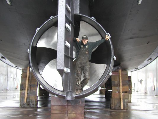
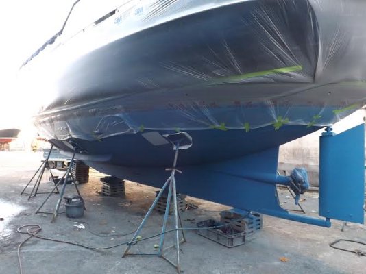
The #4 photo shows a very short flanged affair bolted to a planked wood hull. I can pretty much assure you that that unit and installation is much too small to effect much change. Can’t tell about location and relationship to hull design and length but certainly short on surface area. To the responder who relates installation of bilge keels at the chine and completed in “ one day “ I can’t imagine many vee bottom hulls with a chine deep enough to be effective. BTW chines are a feature of Vee hulls and I have no idea what soft or round chine is. Most all Vee hulls install bilge keels below the chine where there is clean water, at least from my experience and as designed by any of the NA’s I’ve worked with.
With a planked hull be it stripped, cold molded, carvel you need to be very careful constructing proper bilge keels. I’ve done quite a few over the years from 50’ knuckle stern converted fish to 1500 ton MCM USN minesweepers. There are a few hard and fast rules. One is wooden fins should be designed with a sacrificial cap section that will break off on hard impact leaving the root or foundation portion intact and watertight. Through bolting to frames is not advisable as it puts localized stress and compression on the frames and invites water migration and decay into the frame. Ive seen several commercial fish hulls where every bilge keel thru-bolt was loose. The frames gradually compressed or crushed resulting in not only loose bolts but washed out- enlarged holes with soft decayed frame material. Of course large washer plates under the nuts would help but these also create hard spots at edges that can encourage frame breakage unless shaped and fitted to the frame faces. Any butt joint found in way of the bilge keel footprint must be reworked and reinforced, another topic.
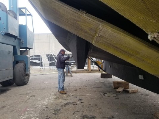
On larger hulls where my crews could work in frame bays we used the following technique. The hull skin in the frame bays is cleaned and prepped for epoxy laminated backing blocks using thin marine grade plywood. I preferred Okoume but there are others. Thickness of these pads depends on hull and service but .75” thick would be minimal. The pad should fit tight from frame to frame and face beveled on sides for drainage. I then construct a saddle that fits atop the inboard face of the backing block and is drilled to accept the bilge keel bolts. This saddle is normally SS plate or channel with side extensions that run over the frames. In essence using the block as a bolting foundation between the frames but tying to the frames. The objective is to take the bilge keel loads and disperse them into the hull fabric. It is unlikely that any bilge stringer will (1) be in the right location and (2) heavy enough to bolt to without problems similar to frame bolting. However if the location is correct heavier or thicker backing blocks could be fitted depth and the stringer used to bridge and consolidate the frames. Or fabricating and installing another stringer for this purpose
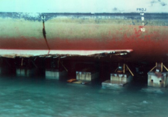
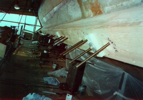
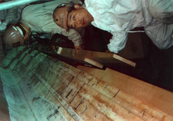
Photos show reef damage to a 225’ USN MCM in Yokosuka, Japan. This is a laminated Doug fir 82’ long bilge keel fully glassed with mat,roving epoxy resin. A view of a laminated backing block with saddle bracket. Shown as an example only.

