Upgrade Twin 30A Power System

The friendliest place on the web for anyone who enjoys boating.
If you have answers, please help by responding to the unanswered posts.

CaptJoe360

Newbie
Joined
Oct 12, 2022
Messages
4
Location
Bremerton
Vessel Name
Hykwa
Vessel Make
Independence 45
I've got a 1988 boat, with a 1988 electrical system. Way too many mods have created havoc. I'm seriously considering a complete rewire, with updated metering, isolation, etc., but keeping the twin 30A shorepower. I like the flexibility and have no 240V loads. I'd like to see some examples of panel diagram for a twin 30A system, plus 8KW 120V genset (60Hz system). Operated on PNW (US and Canada). Thanks!!!
 
Welcome aboard. Are you asking a question? I also like twin 30s. I would go with a new Blue Seas panel. Smart plugs on the power cords. Make sure the neutrals from each shore power are on their own bus and not connected together.
 
Here is how I did mine

Two 30A inlets, each feeding a isolation transformer and then feeding it's own panel.

A third panel for inverter based loads.

A selector switch to feed both 30A panels off of one shore power for situations where you only have one 30A shore power.

The inverter feeds very 120V outlet on the boat,microwave, etc...
 
Joe
Welcome aboard TF
My 2008 Mainship 34HT has 2 -30A inputs and a single panel. The panel has selector / transfer switching that allows separating inputs 1 & 2 or combining to run off 1 only. Very useful in cooler Wx where both ACs aren't needed.
Selector also does the switching to gen as input.
Mine has isolation xfmrs on both inlets and is a very good option especially with an older vessel and new marina electrical codes.
I think I have layout & schematic files for front & rear of panels. If interested let me know and I'll do a little searching and post them.
 
Mine is similar to Kevin’s, but with a couple of small changes. I have two inlets, leading to two isolation transformers and two transfer switches that choose shore power or genset. One panel is strictly off of the shore/gen transfer, the other panel is split so the inverter supplies power to the chosen circuits. I didn’t want any chance of depleting the house bank if someone inadvertently turned on the water heater or electric heaters.
I can start the genset if I need to power those things.
I had to completely rewire the ac power system as the existing wiring was just a mess and unsafe.
If I want to combine the inlets for a single 30 amp cord I do it with a y cord at the inlets.
It takes a fair amount of work to do this right, but the reward is well worth the effort.
I have a hand drawn sketch of this in my documentation file if it would help.
 
Joe
As requested here are the AC panel & switching pics & diagrams I have.

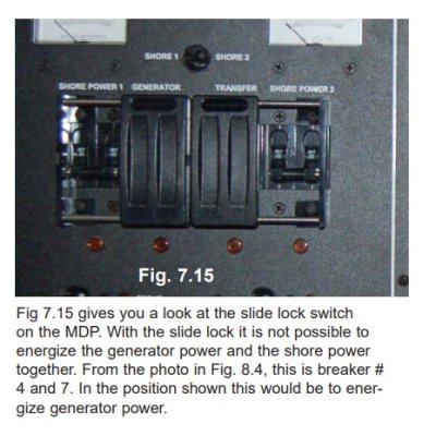
The Pic shows the Pacer AC Panel front with the 2 switch covers for Transfer & Gen shown in their center position. This allows use of 2 30A shore cords connected to inlet #1 & #2 and the Cord #1 powers the left side breakers and cord #2 powers the right side breakers. These switches need to be moved up to power the breakers below each (not shown).

By switching inlet 2 off (down) the transfer sw cover can be pushed to the right and the transfer sw activated (up) - this combines the right (#2) breakers and left (#!) breakers and powers them both from cord /inlet #1

By moving the Gen Sw cover to the left (#1 inlet must be off (down) the Gen Sw can be activated (up) powering the complete panel from the Gen.

Hope that helps

The attached PDFs show the front & back sides of the Pacer AC panel
 

Attachments

  • AC Panel Front.jpg
    AC Panel Front.jpg
    64.1 KB · Views: 25
  • 1003154 REV2 120V Panel.pdf
    176 KB · Views: 22
  • 1003154 120V Panel Schematic.pdf
    322.9 KB · Views: 36
Back
Top Bottom