Victron components, and marina power

The friendliest place on the web for anyone who enjoys boating.
If you have answers, please help by responding to the unanswered posts.

slowgoesit

Guru
Site Team
Joined
May 11, 2019
Messages
3,674
Location
United States
Vessel Name
Muirgen
Vessel Make
50' Beebe Passagemaker
We are cruising down the West Coast of Mexico, enroute to the Panama Canal.
The issue we are having is that for some reason, the marina power in the last three marinas we've stayed at has been really high voltage (Marina Mazatlan, Marina Fanatur, San Blas, and Marina Riviera Nayarit, La Cruz) averages voltage between 132vac and 137vac.

Now to the problem. We have a Victron Isolation Transformer 3600, and a Victron Quattro 12/5000 Inverter Charger.

The Victron Isolation Transformer passes power through with a 5% INCREASE in voltage (to compensate for low marina voltage) according to the manual. So, for example, if the Pedestal voltage is 120vac, the output from the Isolation Transformer will be 126vac. Not a problem most of the time.

Now to the problem. The Victron Quattro 12/5000 will accept input voltage from 90vac to 140vac. Sooooooo when the dock voltage is > 135vac (and in reality, it appears that the high limit acceptable vac is really about 138 or so for the Quattro), the output voltage voltage from the Victron 3600 isolation transformer exceeds the allowable input voltage (138vac ish), and the Victron Quattro refused to pass through voltage, and also refuses to charge the batteries . . . .

So, for the 80% or so time during the 24 hour period that the dock voltage is at it's highest, we can't utilize the dock power . . . .

From what I understand, the 5% "overage" is hard wired into the Isolation Transformer as a function of the number of coils, or windings, so that cannot be changed. Also, the allowable voltage in the Quattro Inverter Charger is not changeable (nor would I really WANT to change that)

Anyone have any ideas of a solution or workaround?

That boost is probably nice in a lot of cases, but not so much in others :-(

The only thing I can think of would be to add a wide-input AC to DC charger like a Victron Skylla. They will accept nearly any input voltage, and charge your batteries. Then you can leave your inverter on to power onboard loads without any over voltage. I think there are side benefits as well having a backup means of charging.
 
The farm boy solution would be to wire around the isolation transformer, or wire the transformer backwards (which would make it step down by 5%). I'm not about to recommend those unless you have very clear knowledge of electrical circuits as the devil will be in the details (I am a farm boy.)

But at the dock, doesn't the bypass relay in the Quattro engage, feeding through dock power? And does it not do that if the AC is considered over voltage? Or is it just the battery charger that rejects it?
 
One other option if electrically inclined or able to find a local electrician, although more typically used at more permanent setups at home docks, is to add a small buck boost "auto-transformer" outside the boat to drop the voltage. Normally you'd use that to raise the voltage due to drop after a long run or boosting 208v to 240v, but they can also drop voltage. This can be hardwired to a shore power cord or rigged with normal plugs so it can be inserted inline. I've even seen these supplied by marinas on occasion when they know their voltage is problematic.

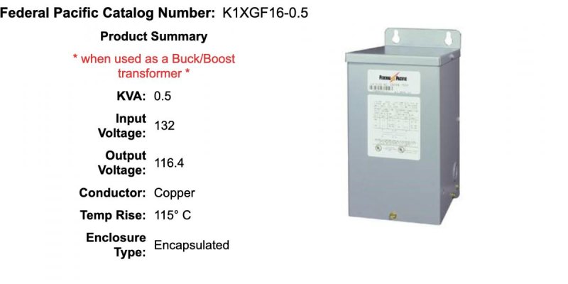
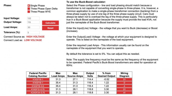
The auto-transformer doesn't mean it is automatic (it will be a fixed percent drop once wired) just that it is "inline" and not isolated, this means a much smaller transformer rating can be used since it doesn't carry the full load. So, as just one example, from the Federal Pacific calculator at https://www.federalpacific.com/tools/buck-boost-transformer-calculator-selector/ , is the 0.5 KVA K1XGF16-0.5 which can be had in the US for a few hundred dollars plus whatever cable and connectors cost for how you wire it.

I didn't think too hard about the exact values I entered into the calculator, you'd want to enter what you think would work best for the ranges you see and confirm the load amps. There are lots of companies that make them, I use Federal Pacific only because they have a nice calculator.

If you were in the US I'd also suggest checking ebay as there are quite a variety of models that can work for a given application, but local electrical suppliers should stock them.

Product Description:
Electrical and electronic equipment is designed to operate on a standard supply voltage. In certain environments the source power may not be at the standard rating for a variety of reasons. When there is variation in the standard supply voltage a Buck-Boost transformer can be used as a simple and economical means of correcting deviations up to ± 20%. When the supply voltage is constantly too high or too low, (usually greater than ± 5%), the equipment may fail to operate at maximum efficiency.

A Buck-Boost Transformer has four separate windings, two windings in the primary and two windings in the secondary. The unit is designed for use as an isolating transformer or as an auto-transformer. As an autotransformer the unit can be connected to Buck (decrease) or Boost (increase) a supply voltage.

Autotransformers are more economical and physically smaller than equivalent two-winding transformers designed to carry the same load. They will perform the same function as two-winding transformers with the exception of isolating two circuits. Since autotransformers may transmit line disturbances directly, they may be prohibited in some areas by local building codes, before applying them, consult local codes.

A Buck-Boost transformer will NOT stabilize a fluctuating voltage.

An encapsulated dry-type transformer is a totally enclosed, compound filled transformer. The core and coil assembly is embedded in a polyester resin compound, which provides solid insulation. The embedding compound has an extremely high heat transfer rate, which permits a design of minimum size and weight. The compound-filled assembly is completely encased in a sturdy steel housing and cannot be damaged by dust, moisture, or adverse atmospheric conditions.

Federal Pacific UL & CUL Listed encapsulated dry-type transformers can be used in industrial, commercial, institutional, and residential installations for economical, efficient distribution of power. Encapsulated units are ideal for dusty industrial areas and are suitable for Indoor and Outdoor applications. Typical loads served include tanning beds, motors, lighting, heating, ranges, air conditioners, exhaust fans, control circuits, appliances, and portable tools.

Federal Pacific encapsulated transformers are designed based on a 25°C ambient, 115°C rise, 180°C insulation system. Due to low enclosure temperature rise, no UL-506 special markings are needed to indicate clearance between the enclosure and adjacent surfaces. Sound level problems are negligible with encapsulated transformers because the core and coils are rigidly encased in the polyester resin, which is mechanically strong and acts as sound deadening material.
 

Attachments

  • Buck-Boost_Transformer_Calculator_Selector_-_Federal_Pacific.jpg
    Buck-Boost_Transformer_Calculator_Selector_-_Federal_Pacific.jpg
    46.4 KB · Views: 33
  • Buck-Boost_Transformer_Calculator_Selector_-_Federal_Pacific2.jpg
    Buck-Boost_Transformer_Calculator_Selector_-_Federal_Pacific2.jpg
    135.9 KB · Views: 41
One other thing I'd try, if you haven't, is seeing if some slips at the marinas have lower voltage and see if you can move to one of those... maybe something at the end of the dock, or on an older dock, or on the same circuit as boats running AC loads 24/7.
 
I would just run on the generator.

some places have sketchy dock power. I have not seen a solution, and there is no way I'm going to re-wire around my isolation transformer as has been suggested.
 
Lots to think about. It's only a problem for us when we are in marinas, and frankly, we prefer to be on the hook.

Whatever solution we end up going with will probably not be applied until down the road, as we are currently in Southern Mexico, and frankly, there isn't availability of marine electricians, and especially, components in any kind of an affordable, or timely manner. We just departed Acapulco, where the services were devastated in Hurricane Otis in October.

From what we could figure out, every marine mechanic, surveyor, etc has left the city in search of work in other locations pending the rebuilding of the marine facilities. Four months after the hurricane, the waterfront still looks like a seen out of an apocalyptic movie.

We're probably only going to be in two more marinas while on the Pacific Coast, Port Chiapas in Southernmost Mexico, where we already have reservations, and Panama City, Panama.

I love the idea of wiring the Isolation Transformer in reverse from an elegance standpoint, but am not willing to risk it in practice.

The other options are also doable except for the availability of hardware here in Southern Mexico.

Lots to research here. Thanks for the replies!:dance:
 
The farm boy solution would be to wire around the isolation transformer, or wire the transformer backwards (which would make it step down by 5%). I'm not about to recommend those unless you have very clear knowledge of electrical circuits as the devil will be in the details (I am a farm boy.)


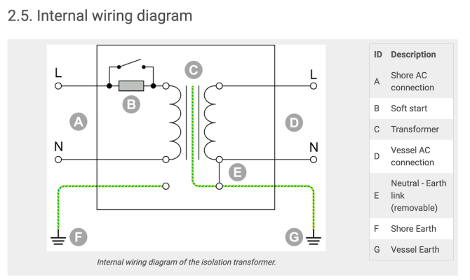
I don't think it is practical to wire it backwards with the Victron transformer, if this is the correct manual for it https://www.victronenergy.com/media...tml#UUID-a1173f15-37c4-15ec-7fe0-c21afecce27b

It is not symmetrical.
 

Attachments

  • 2_ Features.png
    2_ Features.png
    129.4 KB · Views: 42
We are cruising down the West Coast of Mexico, enroute to the Panama Canal.
The issue we are having is that for some reason, the marina power in the last three marinas we've stayed at has been really high voltage (Marina Mazatlan, Marina Fanatur, San Blas, and Marina Riviera Nayarit, La Cruz) averages voltage between 132vac and 137vac.

Now to the problem. We have a Victron Isolation Transformer 3600, and a Victron Quattro 12/5000 Inverter Charger.

The Victron Isolation Transformer passes power through with a 5% INCREASE in voltage (to compensate for low marina voltage) according to the manual. So, for example, if the Pedestal voltage is 120vac, the output from the Isolation Transformer will be 126vac. Not a problem most of the time.

Now to the problem. The Victron Quattro 12/5000 will accept input voltage from 90vac to 140vac. Sooooooo when the dock voltage is > 135vac (and in reality, it appears that the high limit acceptable vac is really about 138 or so for the Quattro), the output voltage voltage from the Victron 3600 isolation transformer exceeds the allowable input voltage (138vac ish), and the Victron Quattro refused to pass through voltage, and also refuses to charge the batteries . . . .

So, for the 80% or so time during the 24 hour period that the dock voltage is at it's highest, we can't utilize the dock power . . . .

From what I understand, the 5% "overage" is hard wired into the Isolation Transformer as a function of the number of coils, or windings, so that cannot be changed. Also, the allowable voltage in the Quattro Inverter Charger is not changeable (nor would I really WANT to change that)

Anyone have any ideas of a solution or workaround?
Check out the recent episode of YT channel Sail Life. They are in Trinidad with the exact same problem and he explains how he sorted it with his Victron gear
 
I appreciate the thoughts, but we're not going to go the route of reversing the Isolation Transformer.

I pulled up Sail LIfe (Athena), but haven't watched it yet. Hopefully it will give us some new ideas. Thanks for the assist(s).:dance:

We are currently about 316 nm out of Port Chiapas (Tapachula) Mexico. We expect to get in there this Friday around noon. Hopefully we don't run into the same issue there! :thumb:
 
I pulled up Sail LIfe (Athena), but haven't watched it yet. Hopefully it will give us some new ideas. Thanks for the assist(s).:dance:

Mads is very clever electronically and explains in detail why he has chosen the route to sort the issue.
Good luck with the solution and I hope your cruise goes well, it sounds like a great adventure.
 
personally, i think twisted tree's suggestion of a wide input battery charger makes a lot of sense. i think your boat is set up to run off the batteries and inverter for house loads, so all you really need from the marina is power to replenish the batteries. (unless there are other other loads the inverter won't handle, like ac)
 
I recently had an auto-boost controller installed on my isolation transformer to deal with low dock voltage. Seems like it ought to be possible to go the other way. Maybe call these guys for ideas: https://www.nauti-tech.systems
 
We had the exact same problem with our Victron Isolation Transformer 3600W Auto 110V/250V using it in Mexico marinas. To solve it, we did what has already been suggested in that we installed a Buck-Boost Transformer. This completely fixed the issue and has been very handy in marinas, not just in Mexico, but across the pacific. I installed terminal strips with terminal strip jumpers next to the Buck-Boost. With a quick change in jumper arrangement, we can change from 120V boost, 120V buck, 240V boost, 240V buck, or bypass the Buck-Boost completely. In Mexico, it's the 120V buck that's needed. Attached is a snippet of that part of our AC electrical flow diagram showing the jumper arrangements. The Buck-Boost wiring arrangement to the terminal blocks was specifically chosen to make jumper changes easy. This is the Buck-Boost we purchased:

https://www.grainger.com/product/ACME-ELECTRIC-Buck-Boost-Transformer-120V-4LEF9

Looks like the price has increased dramatically - maybe shop around if you go this route. It was a simple installation, and it works well. Just depends on whether it's worth the trouble for you.
 

Attachments

  • Buck-Boost-Transformer.jpg
    Buck-Boost-Transformer.jpg
    161.2 KB · Views: 79
That's an interesting idea, that looks like it would work! I'll have to research equipment for later installation!
 
That's an interesting idea, that looks like it would work! I'll have to research equipment for later installation!

If you did it the way I've done, it's not a lot of equipment:
- Buck-Boost Transformer
- 8 terminal block
- 2 terminal block (could combine into a single block with above, but I prefer separate)
- 9 terminal jumpers
- length of wire to bring L1 and N outputs back to the Isolation Transformer
- ring terminal crimps for all the connections

The Buck-Boost Transformer itself is very small since it doesn't carry the full load, and comes with 14 AWG wires for all the leads. All of those will wire up to one side of the 8 terminal block. If you have the space/access to install the transformer right next to the terminal blocks, you can crimp ring terminals right to the transformer leads. The 2 terminal block is for when there is no "issue" with shorepower voltage levels and you want to bypass the Buck-Boost Transformer. In this case, wire L1-in to L1-out and N-in to N-out, and you're back to exactly how you're wired now. So, you'll want to label your L1-in, L1-out, N-in, and N-out wires as those are the wires you will be switching around. If you align the leads like I have, the right side of the diagram shows the actual jumper arrangements in red and where to connect your shorepower hot and neutral wires in/out. For 120V buck and boost, you only need the metal terminal jumpers. For 240V, you'll need 3 small wire jumpers with ring terminals (maybe not necessary for you depending on your cruising grounds).

In Mexico, I was setup for a 12V buck in nearly all marinas as the shorepower was typically >130V. In Samoa I used the boost while on varying low 230V shorepower input. Currently I'm in a marina in Fiji and bypassing the Buck-Boost with 230V input and seeing 120V output from the IT. It just depends...but having the ability to raise or lower the voltage has been handy. The Victron auto Isolation Transformer will only output in the ranges of 88V-130V (115V input) and 185V-250V (230V input), and there's the 5% increase that can make matters worse in some cases.

This could also be done with a massive rotary switch, but it'd be pretty complex and a very deep switch with all the wiring connections. My opinion, but the reality is you're not changing jumpers/wiring often enough to warrant that level of convenience. It takes maybe 5 minutes to rewire the terminal blocks.

Hope that helps!
 
Last edited:
Another, admittedly low tech and less elegant, solution is to just add a second shore power cable. The extra cable length will increase resistance and drop the voltage at the boat. I just transited that coast last season. Really enjoyed Nicaragua. Also western Panama and El Salvador, but Nicaragua was the biggest surprise.
 
Another, admittedly low tech and less elegant, solution is to just add a second shore power cable. The extra cable length will increase resistance and drop the voltage at the boat. I just transited that coast last season. Really enjoyed Nicaragua. Also western Panama and El Salvador, but Nicaragua was the biggest surprise.

You beat me to this solution. I was thinking 2 or more shore cables strung together. We are always told about line loss, use a larger size wire for x distance. 50A cable 150 may well drop 5 volts.
 
With a long cable, you will only get voltage drop if you load the circuit. When the circuit unloads, voltage will go up and inverter will gag. And if you load it too much, voltage will drop and inverter will gag.

The boost-buck transformer is the correct solution, pity that the isolation transformer didn't come with trimming taps. Would add very minimally to the cost, and add a lot of versatility. Trimming taps are very common on transformers for industrial equipment for just this reason.
 
Hi y'All greetings from Little River SC! Same issue - have steel hull so bought Victron Isolation Transformer and realized voltage even after 50ft or so cable the voltage is still 123V plus the 5% would be borderline high. Have not yet tackled issue so I am glad about this thread!

My thoughts were dropping voltage is very simple - right size resistor in series with line cable and you get heat and your drop. (metalbox - in out receptacles - heat dissipation grill shield)
More elegant similar to BuckBoostTransformer a simple voltage divider circuit can be added that allows for variable resistor adjustment/output voltage or multiple dividers for multiple drop scenarios.

Boosting bad input voltage beyond the 5% Victron output - different story - thx @StGermain45 for your post

Have a great one y'all!
 
Scott
Your question on reducing dock power has shown some very astute answers from world cruisers. I've some curiosities.

Kevin's suggestion, referenced by his genset industrial background, seems logical - run your genset. I'd guess your need for dock power is to run your air conditioning as you've got sufficient solar panels for your non AC needs. If this is the case are you set up to bypass your IT and inverter and run your ACs safely off dock power? A separate incoming power cord is old school but not uncommon.

Regarding gensets, a relatives large yacht spent several years in Mexico with high genset run time resulting ; iffy dock power and lots of anchoring out being the reasons.
 
My thoughts were dropping voltage is very simple - right size resistor in series with line cable and you get heat and your drop.

The voltage drop you get from a resistor (or a long cable) is directly proportional to the load, which is highly variable on a boat. Not to mention the risk of fire if there is a large load or a short. This is really the wrong way to go about it.

A transformer with trimming taps doesn't use resistors, rather there are taps which bypass some of the windings, changing its step down or step up ratio.
 
I have a question. I was in the same marina at the same time as Muirgen/Slowgoesit. My digital panel meter (Blue Sea M2) saw the same shore voltage as Muirgen saw. I do not have an isolation transformer. I think Scot tried bypassing his IT but no-go.

Whats going on here? Why did he have issues and I did not (and presumably many other boats)? Can anyone describe in terms a 4-year old can understand?

Peter
 
Hi y'All greetings from Little River SC! Same issue - have steel hull so bought Victron Isolation Transformer and realized voltage even after 50ft or so cable the voltage is still 123V plus the 5% would be borderline high. Have not yet tackled issue so I am glad about this thread!

My thoughts were dropping voltage is very simple - right size resistor in series with line cable and you get heat and your drop. (metalbox - in out receptacles - heat dissipation grill shield)
More elegant similar to BuckBoostTransformer a simple voltage divider circuit can be added that allows for variable resistor adjustment/output voltage or multiple dividers for multiple drop scenarios.

Boosting bad input voltage beyond the 5% Victron output - different story - thx @StGermain45 for your post

Have a great one y'all!

123V + 5% is 129V, if that is unloaded then it will likely sag a bit under load so I wouldn't worry about it unless you have issues. I would be very dubious of trying to use a resister as it will vary depending on load.

As for slowgoesit's original issue, there are a couple of things to check in the Victron config that I forgot to mention and didn't see discussed here yet. You want to ensure UPS function is disabled (unchecked), and AC high disconnect is set to 140v (max/default). You may also want to try increasing AC high connect from 135v to 138v or 139v (max) but be cautious of it flipping on and off frequently if you do so.

I believe "UPS function" is on by default. I'm not confident that will make a big enough difference, but might be worth trying.
 

Attachments

  • VE Configure Grid settings.jpg
    VE Configure Grid settings.jpg
    117.1 KB · Views: 38
123V + 5% is 129V, if that is unloaded then it will likely sag a bit under load so I wouldn't worry about it unless you have issues. I would be very dubious of trying to use a resister as it will vary depending on load.

As for slowgoesit's original issue, there are a couple of things to check in the Victron config that I forgot to mention and didn't see discussed here yet. You want to ensure UPS function is disabled (unchecked), and AC high disconnect is set to 140v (max/default). You may also want to try increasing AC high connect from 135v to 138v or 139v (max) but be cautious of it flipping on and off frequently if you do so.

I believe "UPS function" is on by default. I'm not confident that will make a big enough difference, but might be worth trying.

Of note, Victron's auto switching (115V/230V) version of their 3600W Isolation Transformer will not output over 130V in the 115V mode (and not configurable), so any settings downstream on the inverter won't help. From the Op's original post, it does sound like he has the non-auto version. :thumb:
 
I have a question. I was in the same marina at the same time as Muirgen/Slowgoesit. My digital panel meter (Blue Sea M2) saw the same shore voltage as Muirgen saw. I do not have an isolation transformer. I think Scot tried bypassing his IT but no-go.

Whats going on here? Why did he have issues and I did not (and presumably many other boats)? Can anyone describe in terms a 4-year old can understand?

Peter
In another thread you are having issue with your inverter? Is there a connection here to high voltage.
 
In another thread you are having issue with your inverter? Is there a connection here to high voltage.

Although my DC system is new with a bunch of solar and Victron, the overall topology is pretty much old school. Attached is a picture of my AC selector switch. The workaround for the inverter issue is to hard reset after I've been on shore power. I ran the generator today to charge the batteries and I noticed the fault has not recurred after being on generator AC so something to do with shore power. I do have a galvanic isolator on shore power so maybe an issue there somehow. Workaround is fine and I won't be on shore power for quite a while so not high on the list.

I didn't install an isolation transformer. I don't have room, and frankly, Weebles will be on a lift when she gets to Florida and won't spend much time on shore power. But I was just wondering why Muirgen (and some others) have trouble digesting higher dock voltage when most boats such as Weebles does not. I know very little about this stuff so was trying to learn.

BTW - the percent of cruisers with some sort of power related issue is staggering. We've been running fairly trouble free (touch wood).

Peter
 

Attachments

  • 20240217_145525.jpg
    20240217_145525.jpg
    118.1 KB · Views: 48
I have a question. I was in the same marina at the same time as Muirgen/Slowgoesit. My digital panel meter (Blue Sea M2) saw the same shore voltage as Muirgen saw. I do not have an isolation transformer. I think Scot tried bypassing his IT but no-go.

Whats going on here? Why did he have issues and I did not (and presumably many other boats)? Can anyone describe in terms a 4-year old can understand?

Peter

Well, here's one 4 year old, speaking to another.

Both you guys experienced Mexican grid power with a voltage of about 135 V.

The North American Standard is 120 V. +/- 5%, so 114 to 126 V. Lots of things are designed around this standard.
Mexico does not seem to have the standard quite nailed yet, but they will likely get there soon. Then again, the Cartels just might like things hot!

Victron, the little blue box guy, designs his isolation transformer to accept a maximum input voltage of 130 V, higher than that and it simply shuts down, unless you are dealing with a 230/240 V system and here we are not.
The reason they use 130 V as the high limit shut off may well be that they know that their iso. trans. is going to boost (no way to defeat this) the voltage by 5% to 141 V. max. That in itself is too high in my books as you are now 21 V or 18% above the standard.

Perhaps Mexico is not a big market for Victron so they don't care and their stuff is really designed for the US market where the delivered voltage (better regulation) is reliably 120 V. and usually goes down from there, due to resistance. Things are just fine at 120 V. + 5% = 126 V. Max.

So at anything over 130 V. Slowgoesit is darkship on the grid sourced ac side and even if he had a wide voltage ac powered battery charger (as TT suggested) he would have to power it by a separate power cord from the dock mounted pedestal as there is no grid ac onboard.

You, on the other hand have not bought into that Dutch foolishness (yet) and have no such iso. trans. to shut down. The power at whatever voltage just flows onboard. Everything still works.

However, all is not well at a Voltage of 135 or above. Old fashioned induction motors, (your fridge or watermaker perhaps) your microwave or even incandescent light bulbs (what, are those?) are all going to object to being treated so roughly. Who knows if or when the smoke comes out.

Bottom line, I agree with ksanders, short term, run the genset until you can fit a buck boost transformer. Now think about that, isn't that silly, you first knock the voltage down by 5% just so the Victron iso. trans. will accept it and then it automatically boosts it back up the 5%.

The better fix in my mind would be to in the first place, fit an iso. trans. that has the ability to turn the boost and/or buck off or on, think Hubbell or Acme perhaps. Or stay out of Mexico.
 
There ya go, I just demonstrated the 4 year old in me!

130 V + 5 % is 137 V. not 141 V. as previously stated.

It follows that 21 V. and 18% are replaced with 17 V. and 14%. I think.

Maybe I just turned 5!
 

Latest posts

Back
Top Bottom