wifi honeywell thermostat control unit

The friendliest place on the web for anyone who enjoys boating.
If you have answers, please help by responding to the unanswered posts.

paulga

Guru
Joined
May 28, 2018
Messages
1,133
Location
United States
Vessel Name
DD
Vessel Make
Marine Trader Sundeck 40'
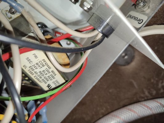
I want to upgrade the thermostat of the reverse cycle AC in the salon to a programmable unit with Wifi connection. There are two other reverse cycles in the boat but this is the one I mostly used. I heard the AC needs to have a "C" terminal for the wifi thermostat to work. But the AC fan has only four terminals - RGWB. Has anyone added a wifi thermostat to a similar AC?

Image_20240626134232.jpg
 
I'm not sure how directly applicable this is to boat AC but I remember dealing with the "no C wire" problem when I installed an Ecobee thermostat at home. There are boxes which will "add" a C wire signal for systems which don't have one. Assuming that a home thermostat interface is used on boat AC systems, they might be of use to you. Here's a link to the Ecobee info re doing that:
 
You might want to double check the voltage and amperage requirements for your thermostat. Not sure if boat AC units run compatible voltage and amperage required for relays (solid state or mechanical).

Ted
 
Inside the box in your photo is the actual control board and no, sorry it's apples and oranges. The controller is completely different than residential hvac and a ribbon cable connection. Micro-Air makes a WiFi stat with 8 wire ribbon cable, but not sure if its compatible. I would talk to their tech support. Can't quite read your label. Is that a Marine Aire unit?
 
Inside the box in your photo is the actual control board and no, sorry it's apples and oranges. The controller is completely different than residential hvac and a ribbon cable connection. Micro-Air makes a WiFi stat with 8 wire ribbon cable, but not sure if its compatible. I would talk to their tech support. Can't quite read your label. Is that a Marine Aire unit?
yes, mermaid reverse cycle AC

Image_20240626202421.jpg


the 4 wires R, G, W, B in post #1 land on RC, G, W, Y terminals on the thermostat. what I heard is, if the AC fan has a C terminal, then the wifi themostat model would work

Image_20240626202416.jpg
 
I need to correct my statement. Looking at the additional picture you attached you do indeed have an older unit that uses a HVAC t'stat but not standard color identification on the wires. The "C" wire that Honeywell refers to is 24vac to power the stat. I assume per your photo is the Red wire connected to the RC and RH terminals, take a meter and confirm what the voltage being controlled is at the stat base.
Hopefully I have successfully attached the install manual, wiring is about page 14
 

Attachments

  • M9INSTALL.pdf
    592 KB · Views: 8
According to that manual, that thermostat will work. It says the thermostat wiring is the standard 24VAC used in home systems. Your problem, just like in home systems, is that older thermostats were just wired as a switch, they didn't have dedicated wires for power.

The solution is to find where the "R" wire connects to the 24VAC transformer, and run a wire to "C" from the opposite terminal off that transformer. You might try calling Mermaid, I suspect they've heard this question many times before and probably have an answer ready. If not, a few minutes taking off covers and chasing wires should get you there. Post pics from inside that box with the RGWB terminals if you need some help.
 
I am no expert and do this at your own risk. The good side is that both home units and yours run on 24v A.C. looking at page 41.

I believe R would be your common or known as your C wire. But you will need to bring a wire up from the other side of the transformer to power the Tstat. But I am thinking there are other controls on the boat's tstat controller.
 
According to that manual, that thermostat will work. It says the thermostat wiring is the standard 24VAC used in home systems. Your problem, just like in home systems, is that older thermostats were just wired as a switch, they didn't have dedicated wires for power.

The solution is to find where the "R" wire connects to the 24VAC transformer, and run a wire to "C" from the opposite terminal off that transformer. You might try calling Mermaid, I suspect they've heard this question many times before and probably have an answer ready. If not, a few minutes taking off covers and chasing wires should get you there. Post pics from inside that box with the RGWB terminals if you need some help.
The thermostat is powered by two AA batteries. if the purpose is a dedicated wire for power, why not use a jumper wire to connect C and RH on the thermostat terminals?
 
Yes, to the above comments. You will need to bring up a wire from the other side of the 24vac transformer to the stat base. This provides stat power independent of the switching functions which is what the Honeywell needs.
 
The batteries only power memory and clock. The older stat only provided switching functions.
 
Yes, to the above comments. You will need to bring up a wire from the other side of the 24vac transformer to the stat base. This provides stat power independent of the switching functions which is what the Honeywell needs.

Got it.
If all it requires is constant 24vac, could the power also be sourced from an outlet using this adapter?
 
Don't know the internal pathways on the Honeywell board well enough to answer.
See a lot of multiple transformer control systems but have also seen boards smoke when plugged in on startup.
 
According to that manual, that thermostat will work. It says the thermostat wiring is the standard 24VAC used in home systems. Your problem, just like in home systems, is that older thermostats were just wired as a switch, they didn't have dedicated wires for power.

The solution is to find where the "R" wire connects to the 24VAC transformer, and run a wire to "C" from the opposite terminal off that transformer. You might try calling Mermaid, I suspect they've heard this question many times before and probably have an answer ready. If not, a few minutes taking off covers and chasing wires should get you there. Post pics from inside that box with the RGWB terminals if you need some help.
I opened the box and snapped some more photos

Barrier terminal - RGWB
IMG20240627222741.jpg


Box inside overview 1
IMG20240627222905.jpg


A closer look of inside
IMG20240627223939.jpg


The lower red wire on terminal position "R" is traced to the one labeled with a green arrow
IMG_20240627_223835.jpg


Where should the "C" wired connect to?
 
The transformer is in the lower right corner of the last 2 photos. Should have 4 wires, the 120 supply and the 24v output. The 2nd wire of the 24 is what you are looking for. Is the wiring diagram on the inside of the cover?

Page 42 of the manual has a schematic. You are looking for the wire that goes from the transformer to the relays. That is what you want to attach to.
 
Last edited:
What Turtle said.

Assuming the wire from the transformer goes to a spade terminal on the relay, you'll want one of these to allow a second connection for your "C" wire:
31sq61ZJe-L._AC_.jpg
 
The transformer is in the lower right corner of the last 2 photos. Should have 4 wires, the 120 supply and the 24v output. The 2nd wire of the 24 is what you are looking for. Is the wiring diagram on the inside of the cover?

Page 42 of the manual has a schematic. You are looking for the wire that goes from the transformer to the relays. That is what you want to attach to.
Thanks for the pdf manual.
I checked page 44 but cannot map the diagram to the physical wiring.


There are four wires on the left side of the transformer - black, white, red, orange. The red and orange wires are both capped in the end, the black and white wires connect to the top right box


IMG_20240628_132420.jpg

IMG_20240628_132938.jpg


Two wires on the right side of the transformer - green and red
IMG20240628131421.jpg

The green wire also goes to the top right box while the red goes to a lower box on the left. Is the red or green the second 24v wire?
IMG_20240628_133405.jpg
 

Attachments

  • IMG20240628131238.jpg
    IMG20240628131238.jpg
    116 KB · Views: 5
Yes the line drawing is only that. It may be helpful to write your wire colors on it to make it more comprehensible to you.
Reading the label on the top of the transformer, it has multiple voltage capability. Common White and 120v Black. 208V Red and 240V Orange being the unused and capped connections. 24vac output being the Red and Green, the two wires you are looking for to make your circuit. Currently one of those wires is common to your relays and the other runs to the stat for switching. It is the wire common to the relays that must be brought to the stat base to provide the power circuit for the stat
 
Back
Top Bottom