Solar help

The friendliest place on the web for anyone who enjoys boating.
If you have answers, please help by responding to the unanswered posts.
Bkay,
Yes, you got right. And it is an example of MPPT efficiency, about a 4% loss through the controller.
 
If you're mounting the flexible solar panels on the Bimini top, you may want to add some type of air-gap between the solar panel and the fabric. The solar panel will get hotter than the fabric will, especially if it is in tropical latitudes. Two options I'm aware of is to put a layer of fiberglass filter material between the panel and the Bimini fabric, then securing the corners of the solar panel to the top. Another option is to put a corrugated sign board under the solar panel, so you have some cross-flow of air between the panel and the Bimini.

The cooler you can run the solar panels, the more power you'll get out of them, and their life will be longer as well.
 
One other question if Pmcsurf1 doesn't mind - I don't think it's too much thread drift.

He shows 87 watts of power from the panel and 83 watts (based on 13.24V times 6.3A) are going into his batteries in "Bulk" charge mode. Is the wattage shown at the panel limited by the lesser of the solar power available OR the power the batteries need? Or is it ONLY limited by solar power?

In other words, when he took that screen shot on a sunny, cool day, is it possible there was more wattage available but the panels didn't accept it because the charger only required 13.24 volts and 6.3 amps due to his batteries state of charge at that time?

Does that question even make sense?
 
Last edited:
Bkay - The answer is both. The Victron controller "pulls" as much power as possible from the panels as is needed for the charge profile of the batteries. i.e. If the batteries were at 100% charge then it would not be "pulling" much power from the panels. If the batteries were discharged then it would "pull" as much as possible from the panels.

I suspect that in Pmc's case it was still early in the morning and although sunny the sun was at a low angle to the panels. That makes a big difference.
 
Bkay, a blurb from the Victron manual:

Battery - State:

Bulk: During this stage the Controller delivers as much charge current as possible to rapidly charge the batteries. When the battery voltage reaches the Absorption voltage setting, the Controller activates the Absorption stage.

Absorption: During this stage the Controller switches to the constant voltage mode, where a pre-set absorption voltage, suitable to the battery type (See section 4.1 Battery Settings below), is applied. When the charge current decreases below the Tail current and/or the pre-set Absorption time has elapsed, the battery is fully charged. The Controller switches to the Float stage. The Tail current is 1A for models 100/20 and smaller; and 2A for larger models. (When an automatic equalisation is being performed this will also be reported as 'Absorption'.)

Float: During this stage the float voltage is applied to the battery to maintain a fully-charged state. When the battery voltage drops below float voltage during at least 1 minute, a new charge cycle will be triggered.

Equalization: This is shown when 'Start equalization now' is pressed in the battery settings. The charger applies the equalization voltage to the battery as long as the current level stays below 8% (Gel or AGM) or 25% (tubular plate) of the bulk current.
 
Here's how I have interpreted that - tell me if I'm mistaken here...

The panels are producing 87 watts. Divide that by 39.22 volts to get 2.2 amps. produced by the solar panels.

The batteries are in bulk mode and the controller is sending 13.24 volts to the battery. So the same 87 watts divided by 13.24 volts is 6.57 amps.

The difference between 6.57 amps and the 6.3 amps the controller is actually sending to your batteries is accounted for by some inefficiency or the power to run the controller. Is that more or less right?
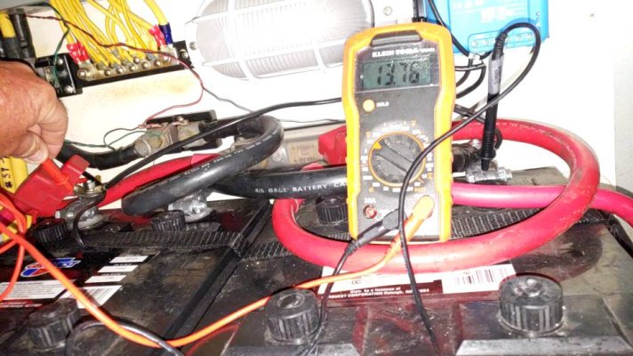
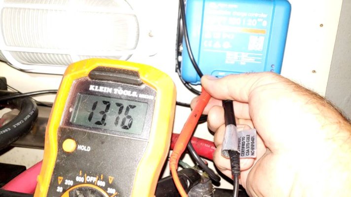
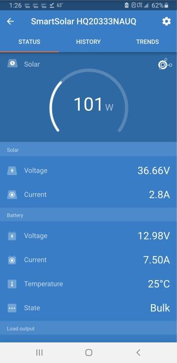
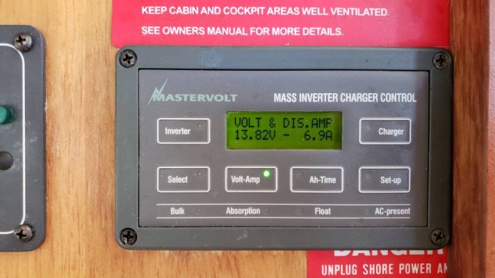
Okay, so the victron app that shows battery IS NOT the battery's voltage. It is the voltage that is being sent to the battery. I took these pics because I was confused why I'm getting different voltage.
First two pics show 13.76 volts at battery and mppt
Third pic is from the app taken at the same time. But only shows 12.98.
The last pic is showing 13.82. Close to the 13.76.
Okay, so the app is showing .70 amps less than all the others. How could the app send less amps to the batteries than they already have? 20201202_132529_capture.jpeg20201202_132452_capture.jpegScreenshot_20201202-132614.jpeg20201202_132855.jpeg
 
Pmc - Assuming that all the meters are fairly accurate I would guess that they are measuring the voltages at different points and that there is a voltage drop somewhere. At this point with my volt meter I would measure the voltage from the negative on the battery to the negative on the output of the Victron. I would do the same on the positive side as well. In both cases the voltage indicated should be 0 V. If you see a voltage in either of those tests then you need to track down where the loss is occuring.
 
Just to follow up, if my math is correct the difference between 12.98 V and 13.76 V is 0.78 V which at 7.5 Amps equals about a 0.1 ohms. You can see that in a connector or two. The 7.5 Amps from the Victron is what it is "putting" into the battery bank. The 6.9 Amps shown on the Mastervolt meter is what the boat is pulling out (discharging) of the battery bank. The other 0.6 amps is adding to the battery bank's capacity.
 
Dog that makes sense. I think I figured out the problem. I bought a Bluetooth voltage and temperature sensor from victron. I thought I needed it to go with the mppt. When I found out the mppt came with it and I didn't need it I stuck it on my generator battery. I think the mppt was getting the voltage from the generator and not from the house bank. I removed the gen sensor and the volts now are only .10 off instead of .7+
Tomorrow when the sun comes up ill verify to see if that's it.
One thing I still don't understand. When my generator is running and the inverter charger is charging the batts the mastervolt panel says charging whatever amps. I dont know why when in solar is making more than being used the mastervolt soc doesn't say charging whatever amps.
 
SOC meters work by measuring the amount of current flowing into a battery bank and the amount of current flowing out. It does that by placing a shunt (small resistor) in series with one of the wires going to the battery and measuring the voltage drop across it.. (Typically the negative wire.) If when you installed the Victron controller you bypassed the shunt and connected it directly to the battery bank then the MasterVolt SOC would not see any of the current coming from your solar panels. The MasterVolt would see the voltage across the battery bank though.
 
When measuring voltages with a portable meter be very carefull that the probes are good ones, are clean and the test areas you are probing are CLEAN. If not you can get goofy readings leading to erroneous conclusions.

For a quick check some error may be ok but if you are asking for accurate results then be sure what you are measuring is CLEAN.
 
SOC meters work by measuring the amount of current flowing into a battery bank and the amount of current flowing out. It does that by placing a shunt (small resistor) in series with one of the wires going to the battery and measuring the voltage drop across it.. (Typically the negative wire.) If when you installed the Victron controller you bypassed the shunt and connected it directly to the battery bank then the MasterVolt SOC would not see any of the current coming from your solar panels. The MasterVolt would see the voltage across the battery bank though.
So is there a way to get the Mastervolt to see what the victron is putting in? Run it through the shunt?
 
Last edited:
Looks like I just need to move everything off neg post to the shunt.
Thanks for you explanation about the shunt.
 
I can confirm the advice of purchasing individual components vs Renogy’s package deal. I purchased Renogy 200 W (2 100 Watt panels, 20 amp MPPT controller, ss mounting brackets and 20 ft cables through Amazon, only to discover later that the individual prices were less money. I also purchased plastic solar panel mounts and fastened them to the top of the pilot house on my Nordic Tugs 32 with 3m 4200 so i did not have to drill holes in the roof. Later I added two additional 100 w Renogy panels and wired two in series and then the pair in parallel. I rarely see over 10 amps on the controller and peak voltage is in the upper 30’s. Also look at RichSolar. The MPPT’s look identical to Renogy at lower cost. Amazon Prime prices are lower than Renogy, but look closely as Amazon will have several prices for the exact same thing from the same supplier. I am pleased with Renogy products so far.
 
I am in the process of replacing my house bank and am going with a Balmar Sg200 SOC meter. It has some really good reviews so time will tell.

Be cautious when installing any shunt based monitoring device, such as the SG200. Make certain that +/- cabling is torqued down good and tight. The tech who installed my SG200 failed to check his work and the SmartShunt overheated and ignited into fire inside my engine room. Thankfully I caught it quickly and extinguished the fire, but damage required $30K in repairs.
 
I have 4 x 100. Found it was actually cheaper to buy individually. Odd.

Make sure your mppt controller has terminals so you won’t be limited by wire size. Some quality name brands such a Victron have distressingly small terminals.
 
I started with their 320 watt flex panels but it wasn't quite enough for my daily load. I didn't have a lot of room to add panels so changed the controller to an MPPT and that gives me all I need and then some. I stopped by today to check in. Attached are the battery monitor readings. This is while under the shrink wrap and with one panel partially shaded. I was still getting 50+ watts. Not enough to light the world but certainly enough to stop self discharge and ghost load even after several cloudy days.


I'm pretty happy but I did have to buy other some components to fit my boat.


Good luck.
 

Attachments

  • 20201207_113727.jpg
    20201207_113727.jpg
    110.5 KB · Views: 30
  • 20201207_113737.jpg
    20201207_113737.jpg
    115 KB · Views: 34
Last edited:
Back
Top Bottom