Voltage drop on ground wire?

The friendliest place on the web for anyone who enjoys boating.
If you have answers, please help by responding to the unanswered posts.

Dougcole

Guru
Joined
Jan 21, 2008
Messages
2,218
Location
USA
Vessel Name
Morgan
Vessel Make
'05 Mainship 40T
I'm planning on moving/rewiring our 1100 Watt portable inverter and have a wiring question. I currently have it wired in to a ground post and a positive post, with a dedicated fuse, under the main helm. These posts come from my house bank. It works OK there, but I have to load shed so as not to trip a breaker. IE, if I plug in the coffee maker while we are running the boat with all electronics powered up, including radar and auto pilot, I trip the electronics breaker on the ER breaker panel.


So I am going to move it closer to the house bank, into a slot that is above my fridge and very close to the main DC panel. I'm also planning on increasing the cable size. There is another positive post there and a negative buss that the panel is wired to, but I think I need to run at least the positive cable directly from the inverter, through a dedicated fuse and to the house bank battery switch.


So here is my question. Assuming I run the positive cable to the ER can I run the negative cable to that negative buss or do I need to ground it on the main ground buss down in the ER? Also, if I use the nearby negative buss can I reduce my cable size? I'd like to shorten/simplify the wire run if possible.


Thanks for the help.


Doug
 
Last edited:
What is the draw from the coffe maker? Why do you think moving it will help? What size wire are you currently using, and how far is it from the battery? What brand is the inverter?

You should place your inverter as close to the battery bank as you can.

Your 1100 watts is roughly 8.x amps Ac , figure it taking 100 amps dc.
 
Most inverters want to have direct connection to battery terminals in order to pull max bat voltage. Your electronic breaker I have to guess is load from inverter.
If that is correct you load after that breaker is overloaded, so I do not see the relationship in moving bat +/-.
 
Most inverters want to have direct connection to battery terminals in order to pull max bat voltage. Your electronic breaker I have to guess is load from inverter.
If that is correct you load after that breaker is overloaded, so I do not see the relationship in moving bat +/-.


The posts and breaker the inverter is currently on have other loads on them as well, most notably all of the electronics. I think when I put a big load on the inverter (like the coffee maker) it overloads the breaker. My thought on moving it is so that I can set up dedicated cables directly to the house battery bank (through a fuse). Moving the inverter makes for a much shorter, much easier cable run. This is not a whole house inverter, it's a portable, albeit a big one, that we plug directly into. The AC side is not wired into the panel in any way.


I guess my question is do I have to have a direct connection on both the + and the - cable? Or can I put the - on a buss with other loads on it?


Sorry for the confusion.


Doug
 
I would run directly to the battery with a size larger cable than necessary. Good voltage is a great thing. No connections to get corroded and cause voltage deop.
 
What is the draw from the coffe maker? Why do you think moving it will help? What size wire are you currently using, and how far is it from the battery? What brand is the inverter?

You should place your inverter as close to the battery bank as you can.

Your 1100 watts is roughly 8.x amps Ac , figure it taking 100 amps dc.


Coffee Maker is a small Kurieg style, it has a max draw of 800 amps.


Inverter is a Kreiger, 1100 watts.


Cables, if I recall correctly are 1/0 from the post to the inverter, either 2/0 or maybe 3/0 from the bank to the posts. Not sure on the run length, my guess is 2o ft each way, maybe a little more. If I move the inverter I could cut that down to about 10' each way.
 
Yes direct connect +/- to the battery so no load side tracks power from inverter.

But still not getting what breaker is blowing. It should be load off AC breaker that exceeds the breaker. BTW, my coffee maker uses 750 watts running, but like most things probably spikes to 1000 on start. So if you already have say 300 on the load it just will not work.

Before you do anything try turning everything else off and brew coffee only. It will likely work.


It works fine when everything else is off, it only trips the breaker when the electronics are running and we turn on the coffee maker. It's a DC breaker, the cable goes from it to the posts that the inverter is currently attached to. It's labeled "electronics" but I'm pretty sure Mainship put other things on it as well.
 
It works fine when everything else is off, it only trips the breaker when the electronics are running and we turn on the coffee maker. It's a DC breaker, the cable goes from it to the posts that the inverter is currently attached to. It's labeled "electronics" but I'm pretty sure Mainship put other things on it as well.
OK, now I am confused. Is the coffee pot plugged in direct to inverter?
DC overload may not allow enough for both inverter and other loads, so coffee maker fail is because inverter does not have the juice to operate. But I still do not get why a DC breaker trips.
Shorter cable direct to battery may still not solve the problem.
 
Without a schematic or sketch, very difficult to follow - not sure what is meant by ER (engine room?) and how that aligns to cabling. Sounds like you cabled the inverter into a positive that is shared, which is a bad idea given the load - your inverter can pull up to100-amps. There is no way your electronics circuit was sized with this type of load in mind. But maybe I have this wrong.

The inverter positive really needs to run to the battery with dedicated breaker and as short a cable run as possible. Much easier and affordable to make long runs of 10-amp 120VAC wire runs (14-guage) than 100-amp 12VDC cable runs (1-awg and 10x the price)

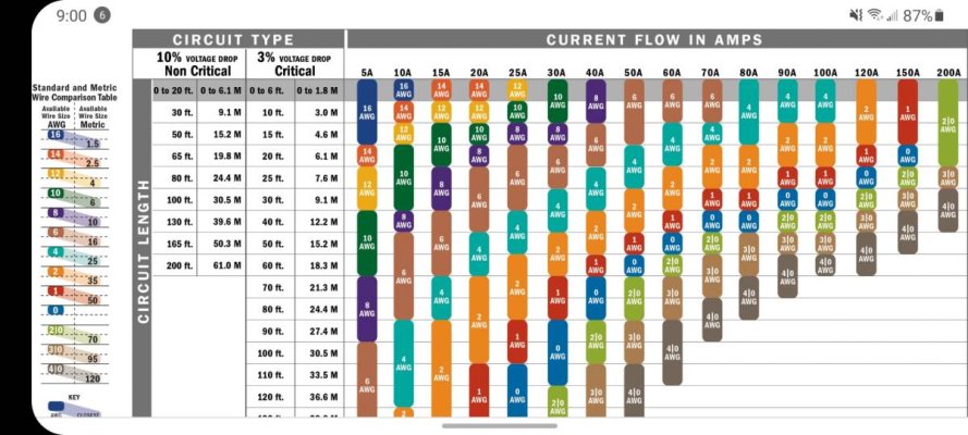
If you're asking if you can run a short negative to a convenient ground but run a long positive to the batteries, answer is yes - but the ground really needs to be a meaty ground. If the ground is then cabled further to the battery, then that total load and length needs to be factored too. The attached Blue Sea cable size chart should be read as the entire circuit length - positive plus negative cable runs (25 feet in this example). If you are running 5-feet of negative and 20-feet of positive for your 1100w inverter (90 amps 12v), you need 1-awg cable at a minimum for 3% loss. There should be a dedicated breaker of 150-amp as near the battery as possible. As an observation, 1100w inverter is pretty small these days and you may want to upgrade. For this example, I'd run 2/0 awg despite the expense to avoid having to rerun larger cable down the road. Breaker should sized for current inverter, not future though.

Finally, no mention about your batteries. I'd guess that well over half the issues I see with mid-sized DIY inverters trace to undersize or old FLA battery banks. There is a surprising amount of voltage drop across the terminals in high draw applications such as an inverter, which is why it's important to eliminate voltage drop across the cables and size them properly. The fact you are tripping a shared breaker tells me you are overloading the breaker. However, it's not unheard of for electronics to shut down due to undervoltage when an oversized inverter load kicks-in and drops system voltage. LiFePO4 batteries can discharge without nearly as much voltage drop which is one of the many benefits compared to FLA.

Good luck.

Peter Screenshot_20220112-023046_Photos.jpg
 
Last edited:
So the title of the thread is voltage drop. But description of issue - breaker tripping - is over current. These are two different issues with only mild crossover (voltage drop could increase amperage to produce same power/watts). What is the problem? Voltage drop or over-current? Are the electronics shutting down due to low-voltage or due to tripped breaker?

Voltage drop will be solved with proper cabling of inverter along with adequate sized battery bank. Over current can be solved same way, but for a different reason. If your battery bank is undersized, no amount of cabling will mitigate voltage drop shutting down your electronics.

More information needed
 
Last edited:
Doug
What I'm gathering from the above and my response... see if I'm correct.
Existing DC wiring for inverter is fed from a DC breaker that feeds electronics (& maybe others ) via a power post where connections split.
No inverter AC connection to distribution panel... only direct plug in
Running electronics w / o inverter OK and no breaker trip
Running inverter w/o electronics OK and no breaker trip
Running inverter ( with any significant AC load) & electronics trip breaker
Am I correct so far?

Question is where to connect inverter to DC to avoid tripping issue?

Inverters should be fused separately and connected directly to batty using adequate wire size (a size larger than min stated w inverter is a good idea). DC run should be as short as possible and wire sizing for 3 % V drop to avoid V drop & increased A draw)
Run length needs to be total distance from and return to battery.
Better to run AC extension cord (proper size for load ) and place inverter close to battys.
If you use a ground bus you need to consider length of run back to batty and is the return cable adequate size to handle ALL the loads connected to it. Better to run dedicated inverter cable.
Others have pointed out the need to have house bank sized for the inverter load and battys charged and in good condition. Any batty weakness will only add to the problems and confuse the situation
If you can't connect directly to batty posts due to # of cables there you may need to add a power post or buss bar to handle multi connections. If so it needs to be close to the batty and all connections/ wires protected by properly sized fuses / breakers.
As others said drawing up a schematic would help clarify things for you by making sure others advising have a clear picture.
Important to use high quality wire terminations especially on the hi A DC inverter cables. Best to order them custom or have someone with the right tools make the terminations.
Here are some tips on batty cables.
https://marinehowto.com/making-your-own-battery-cables/
 
Last edited:
Without a schematic or sketch, very difficult to follow - not sure what is meant by ER (engine room?) and how that aligns to cabling. Sounds like you cabled the inverter into a positive that is shared, which is a bad idea given the load - your inverter can pull up to100-amps. There is no way your electronics circuit was sized with this type of load in mind. But maybe I have this wrong.

The inverter positive really needs to run to the battery with dedicated breaker and as short a cable run as possible. Much easier and affordable to make long runs of 10-amp 120VAC wire runs (14-guage) than 100-amp 12VDC cable runs (1-awg and 10x the price)

If you're asking if you can run a short negative to a convenient ground but run a long positive to the batteries, answer is yes - but the ground really needs to be a meaty ground. If the ground is then cabled further to the battery, then that total load and length needs to be factored too. The attached Blue Sea cable size chart should be read as the entire circuit length - positive plus negative cable runs (25 feet in this example). If you are running 5-feet of negative and 20-feet of positive for your 1100w inverter (90 amps 12v), you need 1-awg cable at a minimum for 3% loss. There should be a dedicated breaker of 150-amp as near the battery as possible. As an observation, 1100w inverter is pretty small these days and you may want to upgrade. For this example, I'd run 2/0 awg despite the expense to avoid having to rerun larger cable down the road. Breaker should sized for current inverter, not future though.

Finally, no mention about your batteries. I'd guess that well over half the issues I see with mid-sized DIY inverters trace to undersize or old FLA battery banks. There is a surprising amount of voltage drop across the terminals in high draw applications such as an inverter, which is why it's important to eliminate voltage drop across the cables and size them properly. The fact you are tripping a shared breaker tells me you are overloading the breaker. However, it's not unheard of for electronics to shut down due to undervoltage when an oversized inverter load kicks-in and drops system voltage. LiFePO4 batteries can discharge without nearly as much voltage drop which is one of the many benefits compared to FLA.

Good luck.

Peter View attachment 124815


Thank you Peter and Soo Valley.


Sorry to be so confusing, even in the thread title. I will try to be more clear.


1. Yes, the coffee pot is plugged directly into the inverter. In the instances of the tripping breaker it is the only load plugged into the inverter.


2. My house bank is 4 6V lead acid batteries which total 440 AH. They are two years old and in good condition, according to my state of charge monitor. I am careful to keep up with water etc.


3. Yes, by ER, I meant engine room. The Mainship 400 has two DC panels, the first panel is next to the fridge in the main cabin. It shares a cabinet with the fridge and you have to pull the fridge out in order to gain access to the inside of the cabinet. There is a substantial positive cable that leads from the battery switch in the engine room up into the fridge cabinet and then to a terminal post. The positive lead from the breaker panel in the cabin is attached to this post. There is also a substantial ground cable that comes from a buss bar in the engine room and leads to a buss in the cabinet behind the fridge.


The second DC panel is in the ER near the battery switches. Certain larger loads, like the windlass are on this second, ER, panel including a breaker that is labeled "electronics." But I strongly suspect that the electronics breaker shares some other various loads as well. It uses a substantial cable as well, I think it is 2/0, and leads to a terminal post under the lower helm. There is also a 2/0 ground cable that leads to terminal post under the lower helm next to the positive post.


Currently, I have DC cables from my inverter wired to the two posts under the lower helm. I am considering moving the inverter into the fridge cabinet. It would be easiest to wire the DC cables from the inverter to the positive and negative posts that are already in the cabinet, but I am afraid I would face the same issue of overloading that circuit when I put a heavy load on the inverter.


So here are my questions.


1. When I put a heavy AC load on the inverter, like the coffee pot, does it increase the DC load as well? Do you think that is causing an overcurrent situation that is tripping the electronics breaker in my current set up?


2. If I run a new positive cable directly to the battery, can I use the negative buss bar that is already in the fridge cabinet for the negative cable? Or should I run a new, longer negative cable to the main negative buss bar in the engine room? If I go with the shorter negative cable run, how do I size the shorter negative cable? Same size as the longer positive cable?


I think you answered this question in your third paragraph, Peter. But since there are other loads on the convenient DC buss, do I calculate all of the loads on that buss? How would I do that?


3. I'd like to be able to shut down the inverter circuit when I turn off the main battery switch, so I'd prefer to wire the positive cable to the switch post rather than directly to the battery. Do you see an issue with this?


Thanks,


Doug
 
Last edited:
Doug
What I'm gathering from the above and my response... see if I'm correct.
Existing DC wiring for inverter is fed from a DC breaker that feeds electronics (& maybe others ) via a power post where connections split.
No inverter AC connection to distribution panel... only direct plug in
Running electronics w / o inverter OK and no breaker trip
Running inverter w/o electronics OK and no breaker trip
Running inverter ( with any significant AC load) & electronics trip breaker
Am I correct so far?

Question is where to connect inverter to DC to avoid tripping issue?


Yes, Don, this is exactly right. Thanks for your response.


Doug
 
Thank you Peter and Soo Valley.


Sorry to be so confusing, even in the thread title. I will try to be more clear.


1. Yes, the coffee pot is plugged directly into the inverter. In the instances of the tripping breaker it is the only load plugged into the inverter.


2. My house bank is 4 6V lead acid batteries which total 440 AH. They are two years old and in good condition, according to my state of charge monitor. I am careful to keep up with water etc.


3. Yes, by ER, I meant engine room. The Mainship 400 has two DC panels, the first panel is next to the fridge in the main cabin. It shares a cabinet with the fridge and you have to pull the fridge out in order to gain access to the inside of the cabinet. There is a substantial positive cable that leads from the battery switch in the engine room up into the fridge cabinet and then to a terminal post. The positive lead from the breaker panel in the cabin is attached to this post. There is also a substantial ground cable that comes from a buss bar in the engine room and leads to a buss in the cabinet behind the fridge.


The second DC panel is in the ER near the battery switches. Certain larger loads, like the windlass are on this second, ER, panel including a breaker that is labeled "electronics." But I strongly suspect that the electronics breaker shares some other various loads as well. It uses a substantial cable as well, I think it is 2/0, and leads to a terminal post under the lower helm. There is also a 2/0 ground cable that leads to terminal post under the lower helm next to the positive post.


Currently, I have DC cables from my inverter wired to the two posts under the lower helm. I am considering moving the inverter into the fridge cabinet. It would be easiest to wire the DC cables from the inverter to the positive and negative posts that are already in the cabinet, but I am afraid I would face the same issue of overloading that circuit when I put a heavy load on the inverter.


So here are my questions.


1. When I put a heavy AC load on the inverter, like the coffee pot, does it increase the DC load as well? Do you think that is causing an overcurrent situation that is tripping the electronics breaker in my current set up?


2. If I run a new positive cable directly to the battery, can I use the negative buss bar that is already in the fridge cabinet for the negative cable? Or should I run a new, longer negative cable to the main negative buss bar in the engine room? If I go with the shorter negative cable run, how do I size the shorter negative cable? Same size as the longer positive cable?


I think you answered this question in your third paragraph, Peter. But since there are other loads on the convenient DC buss, do I calculate all of the loads on that buss? How would I do that?


3. I'd like to be able to shut down the inverter circuit when I turn off the main battery switch, so I'd prefer to wire the positive cable to the switch post rather than directly to the battery. Do you see an issue with this?


Thanks,


Doug
When you plug in your coffee pot, it pulls a heavy DC load. Amps x Volts = Watts. For ease of math, assume your coffee pot pulls 1200 watts. Ignoring losses, you are pulling 10-amps at 120vac to the inverter, then because you have 12vdc, you are pulling 100-amps on the heavy cables. To give some comparison, many windlasses pull around 150-amps tops. So you are definitely pulling a lot of current even with a modest sized inverter.

The manufacturer would likely not recommend it, but connecting the inverter at a heavy battery post such as a battery cable is okay as long as the total length of the cable is correctly sized, including the existing switch-battery cable. If it's 2/0 and you're not pulling heavy concurrent loads, you should be okay. You can get away with it, but I really recommend locating the inverter close to the batteries, then run AC to wherever you want. I've seen plugs for conference room tables used that are essentially an extension cord with permanent outlet such as this one from Amazon. Definitely makes the install look nice and adapts well to future inverter upgrades.
https://www.amazon.com/dp/B071ZG9Q45/ref=cm_sw_r_awdo_navT_g_MG1K4Z9V3YA5D66A5J3A

Your battery bank should be fine unless it's drawn down overnight and coffee in the morning tips it over the under-voltage edge.

How to size the cable. Measure the positive and negative runs of cable and compare the total to the Blue Sea chart I posted above. You will want the 100-amp column if you are sizing for your 1100 watt inverter. In my opinion, you really want to size for 3% loss, not 10%. As mentioned previously, you will have voltage drop across the battery posts - best to keep loss low where you can. Despite expense of cables, they are a one time cost.

Personally, I like a remote on/off switch on an inverter. Not sure how I feel about wiring into a battery switch to act as a simultaneous inverter switch but I confess, I can't argue why it doesn't strike right. But isolating the inverter positive from other loads is a really good first step

Good luck.

Peter
 
Last edited:
If you're asking if you can run a short negative to a convenient ground but run a long positive to the batteries, answer is yes - but the ground really needs to be a meaty ground. If the ground is then cabled further to the battery, then that total load and length needs to be factored too.
Peter View attachment 124815

I believe this is the short answer to your question.
 
If the inverter is not drawing power through the DC breaker that trips ten why is it tripping?
If that DC breaker trips does the inverter stop working? That suggests the buss bar that inverter is connected to is fed from that DC breaker.
 
If the inverter is not drawing power through the DC breaker that trips ten why is it tripping?
If that DC breaker trips does the inverter stop working? That suggests the buss bar that inverter is connected to is fed from that DC breaker.


The inverter is drawing its DC load through the breaker that trips. But the breaker only trips when the inverter is on under a high load AND the electronics are all on. Yes, the buss the inverter is currently wired to runs through that breaker.


Thanks,
Doug
 
The inverter is drawing its DC load through the breaker that trips. But the breaker only trips when the inverter is on under a high load AND the electronics are all on. Yes, the buss the inverter is currently wired to runs through that breaker.


Thanks,
Doug
There is the problem. Do not draw through that breaker, have a separate one or fuse and wire to the battery direct
 
Also, to answer one of your original questions regarding connecting ground from inverter to different post location than the positive and not directly to the battery:

Yes you can, but make sure the wire size for both runs are the appropriate size for the ENTIRE run's length. e.g. if the inverter to the post is only 2 feet, but the post to the battery is 8', you can't use a larger gauge (smaller wire) on that section. You need the proper size on BOTH sections.

As others have said, ideally you would have single wire from battery to inverter with a separate breaker for just the inverter. It would have nothing else on that circuit, and also be as close to the battery as you can. If that puts the Keurig too far away, get an extension cord. If you want to be safe, get an appliance specific cord, smaller gauge.
 
You can take a lot of guess work out of this by purchasing a DC current multi meter. The Flute ones are expensive, but I bought a knock-off a few years ago for about $30. One of the best tools I have. You'll know where all your DC electical consumption is going and if pumps or motors are drawing too much. Connect around your house cable and turn on your coffee maker. You'll know what you're drawing.
 
You can take a lot of guess work out of this by purchasing a DC current multi meter.

Even a simple voltmeter can tell you a lot. Run the inverter at maximum load, and measure voltage between + and - at the battery and at the inverter. If there's more than 0.5v difference between the two readings you've got a wiring problem.

I learned this the hard way on a previous boat. The PO had installed a 1500w inverter to power the fridge, and it worked fine for that. He had used appropriately sized cables and + fusing, but ran the - to a ground terminal near the inverter.

When I started using a coffee maker I noticed the voltage drop at the inverter, but ignored it. Not long after my engine instrumentation started acting up, and the alternator failed. It turned out that the ground path was through a 10 awg wire in the wiring harness for the motor, and that wire had gotten hot enough to melt the insulation off it and adjacent wires in the harness where they were bundled together. Big mess to fix.

I really doubt that the OEM remote ground terminals were designed to handle the additional ~100 amps that the inverter can add to the load. Best practice would be to have dedicated + and - direct connections to the battery IMO.
 
This all seems pretty simple. Too much current is being drawn through the breaker. If the breaker is sized for the existing wire, then it can't be increased. Either shut off the electronics and make the coffee, give the inverter it's own breaker, or wire the inverter to the batteries ( fused) down in the ER and run an AC line up to the coffee maker. Me, being lazy, I'd turn off the electronics.
 
A 1000 watt inverter only draws from the battery, does not charge, (right Doug) so the amps will not be 100A. Probably a 15 amp breaker (guessing)
The problem is solved, the DC breaker tripping was overloaded with both inverter and electronics turned on. one or the other will work fine.
 
A 1000 watt inverter only draws from the battery, does not charge, (right Doug) so the amps will not be 100A. Probably a 15 amp breaker (guessing)

It's good that you're identifying this as a guess, because it's wildly inaccurate.

watts = volts * amps. Check your math. It shouldn't be that hard to understand. Add inverter and cabling loss and battery voltage sag to the mix, and I can guarantee that a 1000 w load on the inverter is going to mean close to 100 amps DC.
 
Back
Top Bottom