Yanmar 370 Alternator upgrade

The friendliest place on the web for anyone who enjoys boating.
If you have answers, please help by responding to the unanswered posts.
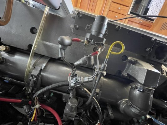
One of the wires to the alternator is typically an "ignition" wire. It goes active when you key-on the engine, and turns on the regulator in the alternator. Next step I would try to figure out which wire that is, and check with a meter to see if it's turning on when you key-on the engine.


A seafire would typically interrupt the ignition for the engine, thereby shutting it down. I could see how that would also kill the Ignition signal to the alternator, but I think it would be odd for it to only kill the alternator ignition signal without also killing the engine.


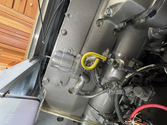
Any chance of a clear, well lit picture of the wiring connections to the alternator? I have zero experience with Yanmars so don't know what's typical.
 
Also a picture of the Seafire box and wiring connections might help. If it's a gray seafire box, they are notoriously failure prone. The black boxes seem reliable.
 
I did confirm that I had power on both the terminal on the T shaped wire plugged into back of Alternator Where do I look to find the Sea Fire box ?? Do not know how to Post Pictures to this site. Bacchus or Done said he posted a link on how to post pictures but it did not appear...At a Total LOSS on this no charge issue.. Read multiple post on this a lot of them hit the nail on the head of what going on but the fix is unclear.. Please Help
 
How to post photos is in the home page of TF in the How to Use the Forum section. There is a sticky post on how to post photos.
 
Jerry
My bad... that will happen at times... here's the link. https://www.trawlerforum.com/forums/showthread.php?t=50850

My local auto elec guy checked my alt and concluded it was fine. He said I need 3 wires connected & reading good...
POS ( output to batty via starter cable ), Neg (ground) and a field excite w +12V when eng key/ switch is ON. It was thec12V excite that ran thruster SeaFore controller and was incorrectly wired. I forget which of the sm GA wires on the plug to the alt was the 12V but that was my issue. The Pis & Neg both have their own stud terminal.
My SeaFire control module is under the helm dash panel and visible with the panel lifted. Not sure how other MS Models are set up / wired.
I just checked the small GA wires at the Alt with eng switch on/off to see if/when I got thev12V to excite the Alt field. Mine hadc12V w Sw off but 0V w/ Sw on... wrong set of contacts on SeaFire. Just swapped and it fixed my issue. Not sure if it your problem but worth checking king to see if you have 2V to excite the field.
 
Last edited:
Some photos of what is installed to charge house bank, engine battery, and both 24v thrusters
 
Naybe this time I got photos
 

Attachments

  • combiner.jpg
    combiner.jpg
    91 KB · Views: 24
  • Battery Isolator.jpg
    Battery Isolator.jpg
    123.7 KB · Views: 28
  • Blue Sea L series Solenoid.jpg
    Blue Sea L series Solenoid.jpg
    119.1 KB · Views: 19
  • Distribution .jpg
    Distribution .jpg
    137.2 KB · Views: 26
First The battery wire on Alternator comes from the A post on the Battery Isolator, not from Starter I verified Ground was good, and had just 12 volts when key or toggle was on, also still had low 12 volt when engine was running... Wanting relay what I have at Alternator
 
Don
I looked under dash at lower helm and did not see a sea fire module. Maybe its under the upper helm dash I will have to look there tomorrow, but I did not see it at lower helm. I thought earlier that it would have been less wire distance to lower helm so that is where I looked... With ignition off I did have a slight voltage 0.015 volts, definitely not zero..
 
First The battery wire on Alternator comes from the A post on the Battery Isolator, not from Starter I verified Ground was good, and had just 12 volts when key or toggle was on, also still had low 12 volt when engine was running... Wanting relay what I have at Alternator
Jerry
That isolator was similar to mine except mine was only for 2 battys vs your 3 banks.
I didn't like the inherent 0.75-1.0V drop associated with diode isolators and I replaced mine w a more modern isolator. Complete write up on my Bacchus website in projects section.
I will guess that your eng start batty lead (#1, 2 or 3) on your isolator goes from isolator to the starter, at least that's how mine was wired to avoid long runs of heavy GA cable.
The A terminal should be 0 when eng off... don't understand how you get 12V as alt isn't providing output and isolator diodes should prevent back flow from any of the battys?
Have you figured out which battys are #1,2,3?
When eng is running at say ~1200 RPM term A should be alt output and around 14V +/-... @12V none of the battys are getting charged?

No idea where MS put your SeaFire controller but found mine by tracing alt excite wire back to find out why it has 12V w eng off and 0V when eng sw activated... the excite wire is one of the 2 light Ga wires that attach via the "L" shaped plug on back of Alt.

I'll bet you are learning from your digging & tracing... I know I did. It's not easy but essential to understand how your system is wired and supposed to work.
I made up a long test wire w clips on both ends so I could disconnect a wire/cable and check continuity with wire & a meter. Just checking V may help but can't be conclusive evidence it's the same wire.
 
Don, Going back down today and check and test again,, going to take notes today.
 
Everyone : read Post 29 again.. At one point I had charge then no charge… ??
 
Jerry
My bad... that will happen at times... here's the link. https://www.trawlerforum.com/forums/showthread.php?t=50850

My local auto elec guy checked my alt and concluded it was fine. He said I need 3 wires connected & reading good...
POS ( output to batty via starter cable ), Neg (ground) and a field excite w +12V when eng key/ switch is ON. It was thec12V excite that ran thruster SeaFore controller and was incorrectly wired. I forget which of the sm GA wires on the plug to the alt was the 12V but that was my issue. The Pis & Neg both have their own stud terminal.
My SeaFire control module is under the helm dash panel and visible with the panel lifted. Not sure how other MS Models are set up / wired.
I just checked the small GA wires at the Alt with eng switch on/off to see if/when I got thev12V to excite the Alt field. Mine hadc12V w Sw off but 0V w/ Sw on... wrong set of contacts on SeaFire. Just swapped and it fixed my issue. Not sure if it your problem but worth checking king to see if you have 2V to excite the field.


Any idea why your SeaFire was wired like this? Did it also kill the ignition to the engine and shut it down as expected?
 
Been checking with test leads and the what I will call the EXCITE wire had no voltage with ign off.. with ign on the exite wire ( vertical wire on alt) had 1.4 volts the L wire or horizontal wire had 12.28…. There is a solenoid on the port side of the 370 yanmar that has two good size wires about same size as the one coming from alt to multi battery isolator… That solenoid snap when ign is turned but voltage did not cross the change from the hot side to out put side… ONCE it snapped a second time and the excite wire had good voltage and alt was charging….. tried to duplicate again and no dice………… I’m thinking that that solenoid is some way connected to the ign circuit…. DOES. Any Yanmar owners know what the purpose that solenoid is for ?????… /We once jumped both the excite lead to the Horizontal lead and alt charged….. I want to fix this properly…
ANY IDEAS ?
 
Going to try to load a pic of solenoid from ipad
 

Attachments

  • IMG_5360.jpg
    IMG_5360.jpg
    159 KB · Views: 24
Another pic with terminals exposed
 

Attachments

  • IMG_5361.jpg
    IMG_5361.jpg
    143.5 KB · Views: 24
Thinking about this solenoid I’m thinking it is for the air heaters that are on Starboard side of engine???
 
Any idea why your SeaFire was wired like this? Did it also kill the ignition to the engine and shut it down as expected?
No engine ran fine. I didn't check all the SeaFire connection to confirm where they went. Only needed to fix the Alt excite wire that went to NO instead of NC contact on the controller. Moved that wire and all was well.
I doubt that is an intentional move by MS rather an error by a tech when building.
The PO of my boat had it for a few yrs but on a rather small lake so couldn't cruise far or long. He basically ran off battys and they recharged when back at his dock. Just a guess but I'm sure he didn't mess with wiring he was about 80 YO and just sat on his boat.


Thanks. I just can’t imagine why anyone would want the SeaFire to shut down the alternator as a separate action from shutting down the engine.
 
Follow up Post... We I confirmed that solenoid was for the Air heater. What caught my eye was the voltage change with it click.... After a couple more hours... It dawned on me that I had been turning engine on and starting from lower helm... So to try and figure this out I went to the upper helm and tried to start engine..The buzzer sounded and I started it and low and behold it was charging.... So down to engine room to check back of Alt.. voltage was 14.4 volts and 13.8 on the Isolator.. Possibly it was the switch at the lower helm.. I believe last owner used the upper helm, I like to use the lower helm.. Time will tell if that was it... Wanted to report on this maybe it will help someone else
Jerry


That's excellent progress. Now you just need to figure out why so you can fix the lower helm.
 
Yes, and to research a different Multi Battery Isolator.. Pure Power 1203 Is losing at least a half a volt . Would like to find something better that is recommended
 
Yes, and to research a different Multi Battery Isolator.. Pure Power 1203 Is losing at least a half a volt . Would like to find something better that is recommended
Have you looked for/at the "charging system upgrades" project summary I posted on my Bacchus website?
It contains a link for a summary of the various alternate technologies available to replace diode isolators. It is basic and a little dated but a decent intro to the options.
I had a concern that if I activated thruster(s) when batty banks were combined could the isolator/ combiner handle a potentially high amp flow between batty banks. The ProIso (my initial choice) tech support advised that their unit was not recommended for my application. The chosen Sterling unit was confirmed as a good application and has worked very well. Once I confirmed yhe Sterling unit I did not investigate others.

The only change I have made since the project summary was to move my engine start from the MS scheme of a combined house/start bank to the thruster bank leaving a pure house bank. At that time I added a Balmar batty monitor to better monitor & manage my batty banks.
 
Last edited:
Don
Yes I did look over your charging system upgrades. I know that things constantly change , some times for the better lol. I was hoping that the group would respond with their ideas . The Battery Monitor looks like a must have addition. And Thank You for your Web Page lots of good Inforation.
Jerry
 
Yes, simple diode isolators lose at least a half volt. Solutions are:

FET diode isolators that have a much lower voltage drop. Not sure if those are still made though.

Automatic Charging Relays from Blue Seas and others- more sophisticated and have no voltage drop.

Battery Combiners from Yandina. Simple, basic and I like their customer service. Also no voltage drop.

David
 
Not wanting to reinvent the entire current charging system, I would just like something that would take the place of the model 1203 Pure Power Multi Battery Isolator.
 
I would fix broken things as a first priority, eg the alternator control issue between your upper and lower helms that is the subject of this thread. Then move on to upgrades and improvements.
 
Kickback,


I just want to make a few comments, hopefully to help. I also had a MS400 for 5 years before getting my MS 430.


First: Balmar does make some find upgrades, but be careful in upgrading as you want to be SURE your wiring will handle your larger alternator. I made the mistake of getting talked into a 250a alternator which was a waste and removed it for a 170a install which is also plenty, but will fit my wiring.


https://balmar.net/application/marine/alternators-charging-kits/


If you have a single, a slightly larger alternator is nice, but not a requirement. I upgraded to a re-designed alternator from marinehowto.com,

Rod Collins, who did an excellent joy of rebuilding the Hatachi alternator. I also got a Balmar 614 external regulator (618 is the lastest). With your AGMs you ABSOLUTELY need an external regulator or you'll over charge them and they won't last!


Second, and most important: Absolutely hire an ABYC electrician to help you diagnose problems and perhaps help you with a new alternator/regulator. You could probably convert your new alternator to an external one. Let the guy train you in diagnosing and caring for your charging system.


Be SURE your isolator will handle the loads. I had one burn up and wasn't fun.


Third: Do you have a single or twin engine? And do you have an inverter?
If no inverter, and you anchor out much, absolutely get one. Can be pricey but worth it.


More later, but need a bit more info from you. And what is your cruising style? Marina to marina, occasional anchoring, or a LOT of anchoring.


The MS 400 is a wonderful boat. Miss mine at times, and loved the times we had it.
 
Back
Top Bottom