Boat just lost ac power..

The friendliest place on the web for anyone who enjoys boating.
If you have answers, please help by responding to the unanswered posts.
It has just been two weeks since my boat is moved to this slip. it was the first time the breaker tripped.

this assembly seems to be a replacement of the pedestal sockets. I would request to change to another slip if the pedestal assembly has issues.


Running 3 heaters, even on a low setting sounds like you would be close to 30 amps.

My experience is, the breakers on the pedestal are not water tight. They don't make one can with stand the marine environment. So over time the dampness gets into them making the harder to trip them by hand.

Point being that they may not trip right away or take a higher load to trip. I have seam them so hard to flip them off that I had to use a hammer and tap them in a off position.

Now internally, I would think ether two things could happen. One, that it would over heat do to the corrosion at lower loads. Or as mentioned, take a high load to trip it.

In any case, if the breaker feels odd in tripping it by hand replace it.

Maybe I should not mentions this problem that I had. But I will. It could go back to the OP problem. Three years ago when I bought my new used boat and summer hit. I turned on the two reverse cycle units. The analog amp meter read 27A. An hour later that power when out on that cord.

I should have mentioned, I have two cords. One for the house and one for the reverse cycle.

I went to the pedestal and smelled something burning, the socket. The terminals and about 1 inch of the wires were corroded. So I replaced the socket and cut the wires back. All good for about 2 weeks. Again the power went out but this time a small amount of smoke from the pedestal.

I went to the Club stock room and got a whole prewired plug assemble. As in https://www.dockboxes.com/product/mpl1124a-50a-20gfci-amber-faceplate-assembly-with-breakers/ But you can get them in many configurations.

After replacing the assemble and turning on the 2 units the amp meter now read closer to 25 amps and after 3 years all good. My thoughts, that there was so much rust in the wiring that made a volage drop and the amperage up.
 
Thanks for the list.
The first one looks nice.. but its jaw only opens to 0.5", so it does not work with the shore power cable, correct?


The right handheld clamp ammeter is like the right footwear. So much depends upon use cases and budget.

One can't go wrong with a fluke. So, if you want to spend ~$300+ start there. Really.

I like this one for the money. Extech's aren't lab equipment. And they aren't Flukes. But I've never killed one. They've always been solid.

This one has a nice small.clamp to get into small places on a boat and does both AC and DC via the clamp:

https://www.tequipment.net/Extech380950.asp#description

This one is similar from Harbor Freight. I buy from harbor freight if I don't mind exchanging a DOA unit and I'm only going to use it a few times. Not lab equipment. And, I've killed plenty. But usually get a few jobs done:

https://www.harborfreight.com/cm610a-600a-t-rms-acdc-clamp-meter-64015.html

To solve exactly your problem you can use an AC-only clamp meter. You don't need DC. So, narrowing the scope saves money:

From the cheap:

https://www.harborfreight.com/400-amp-trms-auto-ranging-digital-clamp-meter-59458.html

To one step above that:

https://www.tequipment.net/Extech/MA440/Clamp-Meters/

To likely locally available:

https://www.homedepot.com/p/Klein-Tools-Digital-Clamp-Meter-AC-Auto-Ranging-400-Amp-CL120/314263058

To the Flukes
 
The wiring is likely the same
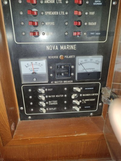
The secondary ac panel is shown in the first photo, according to the illustration, that 120v outlet is "ac pump". I don't know if that's an outlet or a pump.
IMG20231116212126.jpg

IMG20231116212227.jpg

IIRC, you have a Marine Trader 40 Sundeck - basically the same boat as mine with an extra 4 feet of length.

I also have two 30A inputs, but only one of them supplies house power. The other ONLY powers the reverse cycle AC.and one outlet that I haven't located. At some point,.a previous owner added a separate 30A panel just for the AC and that outlet.

You can trace where it goes from the sockets - especially if yours is where mine are - just outside the sliding door into the salon, to the left if you're exiting that door. If that is the case, look for a green wire, white wire, and black wire - all 10 ga - coming from that area inside the boat - the helm cabinet/wiring closet. Mine crossed the deck under the wiring at the bottom of that cabinet.

There should be two bundles - one for each socket.

If your boat is wired like mine, one 30A running the house and one running the air conditioner, you need to know which 110 outlet is powered by the AC circuit because otherwise, you're probably running all the heaters from just one shore power cable, and it's too much for that circuit.
 
Last edited:
I personally think your set up is a disaster in the making. At the very least I would go get two 30a power cords instead of combining separate power lines like you have. Secondly I would never use the type of splitter you are using.

People do things like this because it works the first time but it doesn’t always work as you are currently finding out.
 
The ac panel amperage meters looks like this when all 3 heaters are running on Low with water heater on

So all 3 heaters are running off of one 30a socket. The other socket is pretty much unused.


IIRC, you have a Marine Trader 40 Sundeck - basically the same boat as mine with an extra 4 feet of length.

I also have two 30A inputs, but only one of them supplies house power. The other ONLY powers the reverse cycle AC.and one outlet that I haven't located. At some point,.a previous owner added a separate 30A panel just for the AC and that outlet.

You can trace where it goes from the sockets - especially if yours is where mine are - just outside the sliding door into the salon, to the left if you're exiting that door. If that is the case, look for a green wire, white wire, and black wire - all 10 ga - coming from that area inside the boat - the helm cabinet/wiring closet. Mine crossed the deck under the wiring at the bottom of that cabinet.

There should be two bundles - one for each socket.

If your boat is wired like mine, one 30A running the house and one running the air conditioner, you need to know which 110 outlet is powered by the AC circuit because otherwise, you're probably running all the heaters from just one shore power cable, and it's too much for that circuit.
 

Attachments

  • IMG20231116232003.jpg
    IMG20231116232003.jpg
    168.3 KB · Views: 51
What does it look like when the water heater kicks in. In my opinion you are drawing too much power for the boats wiring. You need to shift some of the heaters to the other power leg.
 
What does it look like when the water heater kicks in. In my opinion you are drawing too much power for the boats wiring. You need to shift some of the heaters to the other power leg.


does that require modifying the wiring? How difficult is that?
 
Paul, respectfully. You have answered in a way that says out loud that you should not be working with the power lines. Get a marine knowledgable electrician involved
 
Paul, respectfully. You have answered in a way that says out loud that you should not be working with the power lines. Get a marine knowledgable electrician involved

I agree with this statement. You will be much better off spending some professional money now. Failure to correct your current situation could easily turn into a boat fire.
 
It would best to run a separate power cord for each circuit. A 30a cord from your 30a pedestal socket to your 30a boat input. Not sure why you have a splitter for two 30a to a single 50a then back to two 30a.

Check all your cord connections for overheating/burning also.

AC pump will be for your air conditioner.
 
Paul, respectfully. You have answered in a way that says out loud that you should not be working with the power lines. Get a marine knowledgable electrician involved

I hate to say it, I have to agree.

What is also being said. From the 2 pics it looks like you are using two splitters (one at each end) on a 50A cord. Why? In other words, Two 30A sockets at total of 60A on a cord that is rated for 50A.

That would be the first thing I would fix!
 
I keep wondering, if the ac units are reverse cycle, why not use them for heat?
Two small space heaters on low will keep things from freezing, add the heating from the ac units for comfort?
 
I keep wondering, if the ac units are reverse cycle, why not use them for heat?
Two small space heaters on low will keep things from freezing, add the heating from the ac units for comfort?

looks like they are reverse cycle. the space heaters already warm up the cabin, so I didn't turn on the ac. ac will run on a routine schedule with the engine and genset - once every two weeks until winterization. actually I was thinking if I should turn off the AC seacocks and winterize them for the winter. there are 3 AC units.
 
I hate to say it, I have to agree.

What is also being said. From the 2 pics it looks like you are using two splitters (one at each end) on a 50A cord. Why? In other words, Two 30A sockets at total of 60A on a cord that is rated for 50A.

That would be the first thing I would fix!

Could you recommend a 30A shore power cable? I'll buy two cables and reconnect if they work
 
Last edited:
does that require modifying the wiring? How difficult is that?

This answer implies that you're unaware of the simplest way to remove the hot water heater from the circuit. Therefore, I have to agree with the others who have said to get an electrician involved.

Have them show you where things are wired and how the panels work.

Electricity - especially AC - is far too dangerous to both you and the boat to be mucking around and learning the basics from conversations on an Internet forum.
 
Could you recommend a 30A shore power cable? I'll buy two cables and reconnect if they work

Curious why you asked for recommendation and also embed a link to amazon showing a 30A cable. Yes, two Marinco 199119 Cordset, 30A 125V, 50', Yellow will work well and give you 60A usuable compared to running thru a 50A cable.
Step 1 and easiest for you to do.
 
Curious why you asked for recommendation and also embed a link to amazon showing a 30A cable. Yes, two Marinco 199119 Cordset, 30A 125V, 50', Yellow will work well and give you 60A usuable compared to running thru a 50A cable.
Step 1 and easiest for you to do.

Thanks for the confirmation.
i saw only one end has a sealing collar. does it requires purchasing two 30A sealing collars for the other end?
 
Thanks for the confirmation.
i saw only one end has a sealing collar. does it requires purchasing two 30A sealing collars for the other end?

The male end seldom has a threaded collar as the pedastal usually does not have one. You pedastal does not have it but your splitters do but are not connected. They are nice to have if you join two cables when a pedastal is not close enough. Otherwise not needed IMO at male end
 
Last edited:
I personally think your set up is a disaster in the making. At the very least I would go get two 30a power cords instead of combining separate power lines like you have. Secondly I would never use the type of splitter you are using.

People do things like this because it works the first time but it doesn’t always work as you are currently finding out.

It would best to run a separate power cord for each circuit. A 30a cord from your 30a pedestal socket to your 30a boat input. Not sure why you have a splitter for two 30a to a single 50a then back to two 30a.

Check all your cord connections for overheating/burning also.

AC pump will be for your air conditioner.

I hate to say it, I have to agree.

What is also being said. From the 2 pics it looks like you are using two splitters (one at each end) on a 50A cord. Why? In other words, Two 30A sockets at total of 60A on a cord that is rated for 50A.

That would be the first thing I would fix!

Well, it seems some people have their knickers in a knot over this.

paulga's first post included a link that showed a Y connector that has a 125/250 V 50 A receptacle. That would mean that the cordset used would contain 4, 6 ga. conductors, 2 that are hot, a neutral, plus the ground. Each hot conductor would only carry up to 30 A (for as long as the plug/receptacle lasts,) while it's capable of carrying 50 A.

So, how is it better/safer to tell the original poster to go buy 2 new 30 A cordsets?
In my opinion the less connections the better. Seems like most cord failures are at the plug ends, and I prefer not to have splitters if it is an option.
 
Well, it seems some people have their knickers in a knot over this.

paulga's first post included a link that showed a Y connector that has a 125/250 V 50 A receptacle. That would mean that the cordset used would contain 4, 6 ga. conductors, 2 that are hot, a neutral, plus the ground. Each hot conductor would only carry up to 30 A (for as long as the plug/receptacle lasts,) while it's capable of carrying 50 A.

So, how is it better/safer to tell the original poster to go buy 2 new 30 A cordsets?

What first post are you looking at?
In this thread the first post shows a 3 wire splitter.
 
The male end seldom has a threaded collar as the pedastal usually does not have one. You pedastal does not have it but your splitters do but are not connected. They are nice to have if you join two cables when a pedastal is not close enough. Otherwise not needed IMO at male end

Thanks for the clarification
 
In my opinion the less connections the better. Seems like most cord failures are at the plug ends, and I prefer not to have splitters if it is an option.

What first post are you looking at?
In this thread the first post shows a 3 wire splitter.

CharlieO

While I agree with you on the "less connections the better" aspect of things, running 25 Amps (about all an L5-30 connection can tolerate) through a SS1-50 connection (about half capacity) can hardly be seem as risky.
Additionally, using the 50 Amp cord's 6 ga. conductors results in less voltage drop when compared to the 30 Amp cord's 10 ga. conductors.

SteveK.

That would be Post #1 dated the 15th of Nov. Look carefully for the underlined three words in the 2nd last line. The splitter shown therein has a SS2-50R on it.
 
so my current shore power cable is good as it is?
the amperage would be lower than if using two 30amp cables, so it's less prone to over heating?


CharlieO

While I agree with you on the "less connections the better" aspect of things, running 25 Amps (about all an L5-30 connection can tolerate) through a SS1-50 connection (about half capacity) can hardly be seem as risky.
Additionally, using the 50 Amp cord's 6 ga. conductors results in less voltage drop when compared to the 30 Amp cord's 10 ga. conductors.

SteveK.

That would be Post #1 dated the 15th of Nov. Look carefully for the underlined three words in the 2nd last line. The splitter shown therein has a SS2-50R on it.
 
paulga.

Nobody here knows if your current shore power cable "is good as it is!"

As long as everything is in good shape, your existing shore power delivery system (2 Y connectors and one 4 conductor cordset) is unlikely to be improved upon.

Historically the limiting component is the 30 Amp. receptacles/plugs at the shore pedestal and at your boat. The male plug often suffers from a corrosion induced high resistance connection with the female receptacle that produces heat, which simply makes the connection worse over time. Loss of the built in clamping tension in the female receptacle from the heat accelerates the demise of this rather poor design.

You would be well advised to keep everything clean, dry, tight and monitor the heat at the connection, just carefully by hand is sometimes good enough to tell if there is a problem brewing.

The pedestals receptacle is often the worst, but as it's not yours it's difficult to service.

Your 4 conductor 50 Amp, 50 foot+/- cord could be fine as it will be running at about half capacity. The larger 50 Amp connectors on this cord need the same attention as the smaller 30 Amp connectors, clean, dry, tight. They are simply more robust.

The current that the connections to the boat are required to safely pass will likely be less in your present set up IF everything is in good shape, simply due to the larger conductors in the 50' 125/250 50 Amp. shore power cable. This benefit is small and basically always in your favour, but it pales in comparison to one or more bad connections. In short, wire size seldom changes on its own, connections are notorious for environmental degradation. Be diligent with the connections.
 
Are you using your water heater? Is the breaker turned on and will the heating element b energized when the water gets below a certain temperature? I ask because I learned that lesson years ago. My heater draw was ok, but then without me knowing it the hot water heater would turn on blowing breakers when "nothing" had changed.
 
Thanks for all your inputs.
will ask around how to distribute the load to the other socket
 
Are you using your water heater? Is the breaker turned on and will the heating element b energized when the water gets below a certain temperature? I ask because I learned that lesson years ago. My heater draw was ok, but then without me knowing it the hot water heater would turn on blowing breakers when "nothing" had changed.

yes, the hot water breaker is left on.
water is otherwise too cold.

do you not use water heater?
 
..............

SteveK.

That would be Post #1 dated the 15th of Nov. Look carefully for the underlined three words in the 2nd last line. The splitter shown therein has a SS2-50R on it.
Thought it was the 50A 125V cord.
Thanks Luna, I did miss that. Then depends on the pedastal whether the two 30A are in phase or not. The 50A 4 wire cable is capable of 240V. Still potential of two 30 amp output drawn on a 50A cable
 
Back
Top Bottom