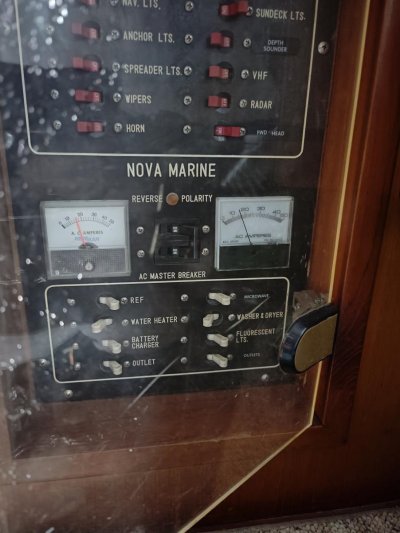
Boat just lost ac power..

The friendliest place on the web for anyone who enjoys boating.
If you have answers, please help by responding to the unanswered posts.
Thanks.
no worries, I haven't done and don't plan to do any mod to electric wiring system. i'm on boat daily, will keep an eye on the gauges /meters closely and remotely.

This is the biggest issue for me. If it were just him and his boat parked behind his house - have at it. But in a marina, you have more responsibilities than just your own boat. If one boat catches fire and can't be quickly moved away, it's a near certainty that if it gets out of control, the boats around it will also catch fire, and if the marina is crowded, it could easily burn the whole thing down.

That could ruin the lives of many people and is something no amount of insurance could recover.

In that situation, if you don't know 100% what you're doing - don't do it.
 
Breaker Trip

U didn't indicate whether this is Your dock or a Rental. A single trip on a dock, where their are multiple boat is hard to find, with no other information.
If this turns into a multiple event, have the owner fix it or if it is yours, hire an Electrician. ( Cheaper,in the long run)...Good Luck,


Ken Ongemach MSEE
 
It has been running fine, but the same pedestal breaker just tripped several times.

I borrowed a fluke 325 to measure the current, but the reading does not make sense, 0.14amp for a space heater is too low. The voltage reading is also constant 0. I don't know if I got a lemon or have I missed anything.

I adjusted the thermostat a bit lower, now the loads of the two sockets looks like below

IMG20231126003137.jpg
 
Are you still using the same power cord set up?

Changing the thermostat does not change the wattage on your heater. 1500 watts is 12.5 amps. Your water heater is another 12.5 amps. Two heaters and the water heater would max you out, add your lights and you are over 30 amps.
 
I tuned the water heater off over a week ago.
The lights and water pumps are on DC lines powdered from battery. So they are not affected by the tripping.

A total of 4 heaters are working. The heater in the v berth and sundeck are connected to one socket (the secondary AC socket for reverse cycle ac units). Bilge heater and aft cabin heater are connected to the other socket. It has been ok for 10 days. I don't know what happened last night, the breaker tripped multiple times.

I reduced the thermostat of bilge heater to min (oil heater, antifreeze setting), and also of the other heaters. No more trippings so far.


Are you still using the same power cord set up?

Changing the thermostat does not change the wattage on your heater. 1500 watts is 12.5 amps. Your water heater is another 12.5 amps. Two heaters and the water heater would max you out, add your lights and you are over 30 amps.
 
The fluke meter needs to clamp on a single wire. Either the hot or the neutral. Then there could be a scale selector to move the decimal point
Really though, it looks like your analog meters are working, if you’re staying in the less than 20 amp range, you might have a weak breaker on the dock.
 
The fluke meter needs to clamp on a single wire. Either the hot or the neutral. Then there could be a scale selector to move the decimal point
Really though, it looks like your analog meters are working, if you’re staying in the less than 20 amp range, you might have a weak breaker on the dock.

So the 325 fluke does not read volt or amp if I clamp around the lines of a heater, or the shore power cable? Area behind the wall sockets are simply not accessible
 
So the 325 fluke does not read volt or amp if I clamp around the lines of a heater, or the shore power cable? Area behind the wall sockets are simply not accessible

Please take a look back at my posts 87 and 88 in this thread.

If you clamp around the whole cord, the ammeter will read the net current flow, which is the leakage, the amount of current flowing in via the cord by flowing out somewhere else, like the water, vs back through the cord. If that is really 0.140A of leakage, that is a lot, possibly unsafe for swimmers/divers, and will likely trip the GFCI at a modern dock. That is a different issue, which also requires investigation for safety reasons.

Adjusting the thermostat on those heaters usually causes them to come.on less often, but doesn't change the draw when they do. Sometimes there is a Hi-Med-Low switch that will change the draw. So, it reduces the likelihood that all three will collide and be on at the same time -- but you can still get that dice roll.

You can, in theory, measure AC voltage in a touch less way. But, getting an accurate read vs an approximate one is very difficult. Most volt meters require touching the terminals and just detect voltage touch less.

You really might want to get some help with this...
 
All heaters were running at the same time last night, after the last time i reset the breakers. I don't know exactly why it has not tripped since then.

The ac voltage reading stays 0 when I clamp around the heater line. So this 325 does not work?


Please take a look back at my posts 87 and 88 in this thread.

If you clamp around the whole cord, the ammeter will read the net current flow, which is the leakage, the amount of current flowing in via the cord by flowing out somewhere else, like the water, vs back through the cord. If that is really 0.140A of leakage, that is a lot, possibly unsafe for swimmers/divers, and will likely trip the GFCI at a modern dock. That is a different issue, which also requires investigation for safety reasons.

Adjusting the thermostat on those heaters usually causes them to come.on less often, but doesn't change the draw when they do. Sometimes there is a Hi-Med-Low switch that will change the draw. So, it reduces the likelihood that all three will collide and be on at the same time -- but you can still get that dice roll.

You can, in theory, measure AC voltage in a touch less way. But, getting an accurate read vs an approximate one is very difficult. Most volt meters require touching the terminals and just detect voltage touch less.

You really might want to get some help with this...
 
Last edited:
The ac voltage reading stays 0 when I clamp around the heater line. So this 325 does not work?

The clamp can only read net AC amperage, not voltage. For voltage measurements, you need to use then probes.

Current flow produces a perpendicular magnetic field. When the current flow changes, the magnetic field changes. This changing magnetic field is called flux. If a circuit passes through magnetic flux, the changing magnetic field acts as a pump and induced a current flow through the circuit that crosses it.

Voltage is potential energy. It isn't activity. It can't be measured by itself. The way it is measured is to allow a very small, current flow through the probes, and use that to determine the voltage. In order meters the current used magnetism to deflect a needle. In modern meters it operates an amplifier. But at a high level it works because there is a relationship between voltage, current, and impedence that can be used to determine one given the other two.

Touchless voltage sensors usually work by detecting small current flows, for example, by participating in the circuit without touching it via capacitive coupling.

I really think you want to do some reading (see my earlier suggestions) and get some help with this...really.

Playing with sparky can be dangerous for both those doing the playing -- and others nearby, immediately and in the future.
 
Last edited:
Thanks for the background theory.
Fluke 117 has non contact voltage function so I thought 325 also has it

The clamp can only read net AC amperage, not voltage. For voltage measurements, you need to use then probes.

Current flow produces a perpendicular magnetic field. When the current flow changes, the magnetic field changes. This changing magnetic field is called flux. If a circuit passes through magnetic flux, the changing magnetic field acts as a pump and induced a current flow through the circuit that crosses it.

Voltage is potential energy. It isn't activity. It can't be measured by itself. The way it is measured is to allow a very small, current flow through the probes, and use that to determine the voltage. In order meters the current used magnetism to deflect a needle. In modern meters it operates an amplifier. But at a high level it works because there is a relationship between voltage, current, and impedence that can be used to determine one given the other two.

Touchless voltage sensors usually work by detecting small current flows, for example, by participating in the circuit without touching it via capacitive coupling.

I really think you want to do some reading (see my earlier suggestions) and get some help with this...really.

Playing with sparky can be dangerous for both those doing the playing -- and others nearby, immediately and in the future.
 
Thanks for the background theory.
Fluke 117 has non contact voltage function so I thought 325 also has it

Not exactly. It has non-contact voltage /detection/. It does not report a voltage value without using the probes. How much voltage is required for it to show the presence of voltage depends upon the distance between it and the wire and the level of shielding.

Right up against a bare wire, I think it can alert as low as 24v. Back away from the wire and more voltage is required to trigger. Add any level of shielding, and even more voltage is required.

It is designed for a quick safety check, not measurement.

Please study some and get some help. This stuff is complex and nuianced and it is super easy to misunderstand and make assumptions without realizing it -- and that can get folks hurt.
 
Thanks for the background theory.
Fluke 117 has non contact voltage function so I thought 325 also has it

Fluke has a myriad of different meters so tradespeople can choose the functions they need the most. Limiting the meters functions let’s them maintain the high quality they’re known for.
You need to choose carefully so you get the functions you want.
 
Fluke has a myriad of different meters so tradespeople can choose the functions they need the most. Limiting the meters functions let’s them maintain the high quality they’re known for.
You need to choose carefully so you get the functions you want.

It should be note that the myriad of different meters Fluke has does not include a meter which will measure voltage without contact, beyond detecting its presence.

The capacitive coupling used for detection is a function of three properties:

capacitance = permittivity * area / distance

In this situation, two of the three (permittivity and distance) are obviously not quantifiably knowable from the perspective of the meter, and even the area isn't known since only one plates is within the meter (the other is the voltage source). The operator can't really input these as parameters, because, although the operator may or may not know or be able to estimate the distance, the operator isn't going to know, or be able to estimate, the permittivity and/or the effective plate area.

In situations such as this, all that is known is that the strength of the coupling, in Farads, will increase as the distance shrinks, until the voltage is sensed and can be indicated.

Doing better using this mechanism would require, somehow, getting a distance measurement between the meter and voltage and getting a quantitative understanding of the behavior of the substances between the meter and the voltage source with respect to their collective permittivity as a dielectric, as well as getting a quantitative understanding of the effective area of the coupling, or, at the least, a quantitative understanding of those properties combined.

I'm not saying that this is impossible. But, it is my belief that no commonly commercially available meter does this for general application.

It would be different if the goal were to measure voltage at a fixed depth in a known substrate, or to bucket it into well separated buckets when measuring across a relatively small range of distances and environments, etc. Limiting the problem domain may provide viable options not available otherwise.

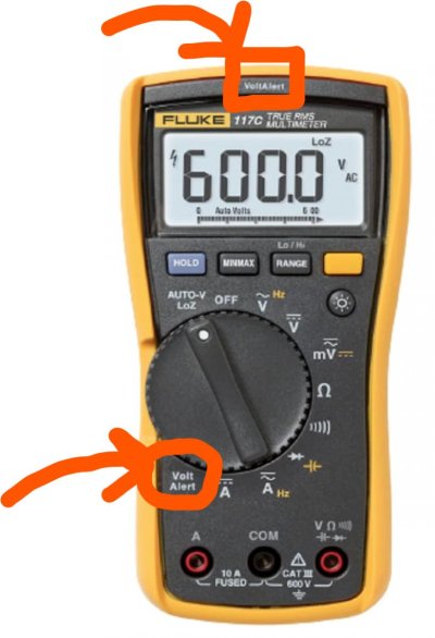
See attached for a picture of the Fluke 117, with the "Voltage Alert" setting and LED identified with annotation.
 

Attachments

  • Fluke117VoltageAlert.jpg
    Fluke117VoltageAlert.jpg
    73.6 KB · Views: 18
Last edited:
You need a "clamp-on" ammeter. The clamp has to go around only the black wire to get an accurate reading. You will have to clamp around the boat side of the shore power connection where the leads are separate. Clamping around the whole shore power cable will only give you a tiny amp reading because the current in the white wire will cancel out the current in the black.
Example:

https://m.media-amazon.com/images/I/51+3R6O-QYL._SL1500_.jpg
 
Last edited:
The clamp can only read net AC amperage, not voltage. For voltage measurements, you need to use then probes.

Current flow produces a perpendicular magnetic field. When the current flow changes, the magnetic field changes. This changing magnetic field is called flux. If a circuit passes through magnetic flux, the changing magnetic field acts as a pump and induced a current flow through the circuit that crosses it.

Voltage is potential energy. It isn't activity. It can't be measured by itself. The way it is measured is to allow a very small, current flow through the probes, and use that to determine the voltage. In order meters the current used magnetism to deflect a needle. In modern meters it operates an amplifier. But at a high level it works because there is a relationship between voltage, current, and impedence that can be used to determine one given the other two.

Touchless voltage sensors usually work by detecting small current flows, for example, by participating in the circuit without touching it via capacitive coupling.

I really think you want to do some reading (see my earlier suggestions) and get some help with this...really.

Playing with sparky can be dangerous for both those doing the playing -- and others nearby, immediately and in the future.

Yeppers. See post 87. I think the OP might just be new at this and need some study time and in-person help to absorb it all and work out the issue he posted about, figure out why there seems to be 140mA of leakage (Many ELCIs trio at 30mA and many shore power GFCI breakers trip at 5mA) , and check over the whole boat.

It is hard to make sense of this stuff bit by bit without a good model for electricity and the idioms used for distribution, in general, and jn boats, in particular. The space gets filled with seemingly random rules for what to do, when, and how, and it is hard to get it right and easy to fall into new space without knowing it. I think, at the least!
 
Thanks for reiterating the correct way of using the meter

You need a "clamp-on" ammeter. The clamp has to go around only the black wire to get an accurate reading. You will have to clamp around the boat side of the shore power connection where the leads are separate. Clamping around the whole shore power cable will only give you a tiny amp reading because the current in the white wire will cancel out the current in the black.
Example:

https://m.media-amazon.com/images/I/51+3R6O-QYL._SL1500_.jpg
 
All heaters were running at the same time last night, after the last time i reset the breakers. I don't know exactly why it has not tripped since then.


I'm not sure you are understanding how heaters like this work. Even with the switch ON, they aren't always drawing power. They will draw for a while, then stop for a while, then draw, cycling on and off like that. That's how they regulate temperature. A hot water heater works the same way, through I think you said yours was off.


There are two ways to figure out what a heater draws when it's actually cycled on and is drawing power.


1) Turn it off and let it cool down. Then look at your ammeter and note the value, then turn on the heater and note how much the ammeter goes up. Because the heater has cooled down, it will cycle on to heat up, and that increase on the meter is the draw of the heater when it's cycled on.


2) Look at the nameplate rating. Look for the current rating, or if it's only listed in watts, then divide that by 110V to get current.


When multiple things cycle on at the same time, and stay on long enough, you are at risk of breakers tripping. It will be seemingly random, as your experience is. A "weak" shore breaker is certainly a possibility, but I think actual overload remains the most likely cause.
 

Latest posts

Back
Top Bottom