HeadedToTexas
Guru
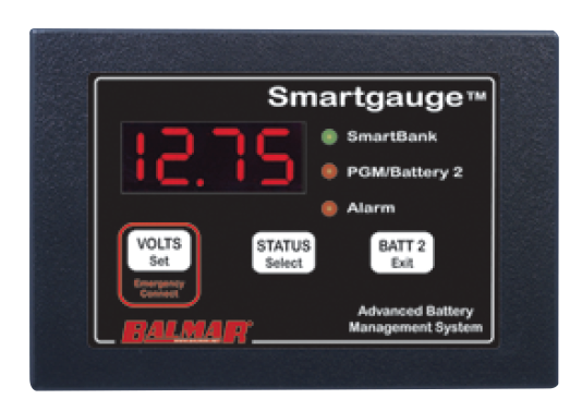
According to our Balmar Smartgauge, the house bank on our 2007 Mariner had gone to zero State of Charge twice. The toll that took on the 2019 AGMs fit with what I was seeing on the Smartgauge as the SOC dropped while at anchor. Believing that an entire electrical system renovation was in our near future, I had not dug into the current battery and charging system to the depth I perhaps should have. It made sense until it didn't.
Neither the voltages displayed on the Xantrex Freedom SW 3000 panel not its bar graph of battery capacity jibe with the SOC on the Smartgauge. Believing that the superior design and engineering of the Balmar product meant it outranked the simple voltmeter and whatever Xantrex uses to make its bar graph, I ran the generator each morning and evening on anchor. One quiet morning, I made coffee on the inverter and it handled the load just fine according to the voltmeters and bar graph. Now, a year or so later, I can anchor two nights with the only charging event being a 90 minute main engine run between anchorages. Balmar says "maybe the Smartgauge needs to be reset?" Perhaps, or maybe my AGMs are good enough?
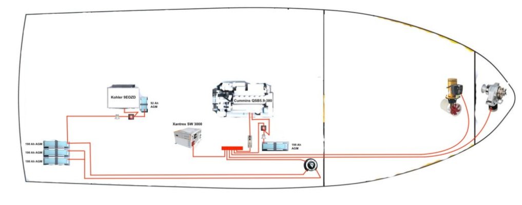
Making several electrical diagrams helped me to understand how the components all fit together, but chasing all those cables through the bilge to create the boat shaped diagram below is what it took to finally grasp the two bank approach. The 3 big 8Ds in the lazarette are divided into 2 banks that include the smaller generator start battery.
The banks are combined 20 cable feet forward at the 1-2-Both switch which is virtually always set to Both. Am I missing something by leaving this switch on both, or have I just not yet encountered the reason to leave one bank isolated by setting the switch to 1 or 2?
The generator battery is isolated behind an old Blue Sea automatic charging relay. The main engine 8D start battery is also isolated by an ACR. When the voltages are right and the Cole-Hersee is set to Both, do those ACRs not combine all 5 batteries into one large (198 Ah x 4 + 92 Ah = 884 amp hours) bank? The batteries all meet at the positive bus.
Neither the voltages displayed on the Xantrex Freedom SW 3000 panel not its bar graph of battery capacity jibe with the SOC on the Smartgauge. Believing that the superior design and engineering of the Balmar product meant it outranked the simple voltmeter and whatever Xantrex uses to make its bar graph, I ran the generator each morning and evening on anchor. One quiet morning, I made coffee on the inverter and it handled the load just fine according to the voltmeters and bar graph. Now, a year or so later, I can anchor two nights with the only charging event being a 90 minute main engine run between anchorages. Balmar says "maybe the Smartgauge needs to be reset?" Perhaps, or maybe my AGMs are good enough?
Making several electrical diagrams helped me to understand how the components all fit together, but chasing all those cables through the bilge to create the boat shaped diagram below is what it took to finally grasp the two bank approach. The 3 big 8Ds in the lazarette are divided into 2 banks that include the smaller generator start battery.
The banks are combined 20 cable feet forward at the 1-2-Both switch which is virtually always set to Both. Am I missing something by leaving this switch on both, or have I just not yet encountered the reason to leave one bank isolated by setting the switch to 1 or 2?
The generator battery is isolated behind an old Blue Sea automatic charging relay. The main engine 8D start battery is also isolated by an ACR. When the voltages are right and the Cole-Hersee is set to Both, do those ACRs not combine all 5 batteries into one large (198 Ah x 4 + 92 Ah = 884 amp hours) bank? The batteries all meet at the positive bus.
Attachments
Last edited: