TheLake
Veteran Member
- Joined
- Oct 16, 2021
- Messages
- 58
- Vessel Name
- The Lake
- Vessel Make
- 42' CHB Tricabin
Hi there.
I finally have my engine (at least one of them) back running (yay!!) after rewiring them. (Perkins 6.354)
Everything looks good, except I can't get a reading on the oil pressure gauge and am thinking I might have wired it up incorrectly.
Here are the symptoms and wiring:
- power on to panel and the needle goes full deflection to 80 psi (this is with nothing hooked up to it)
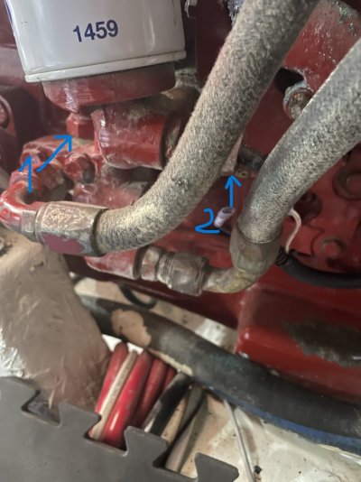
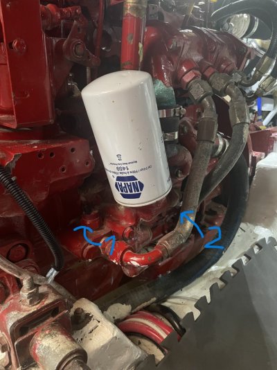
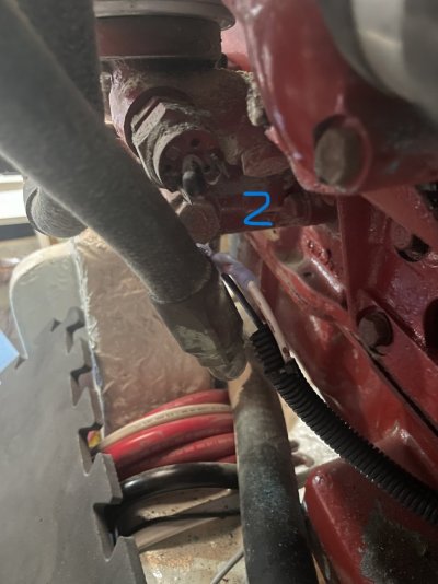
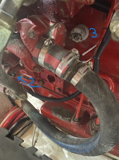
- I have 3 senders/switches. See diagrams. I believe that 3 is the sender.
- The other two I believe are oil temperature and oil pressure switches for the warning lights
So...my questions are:
1. am I correctly identifying the switches versus the sender? (and is there any clues as to which switch is for pressure and which is for temp?)
2. how do I figure out the wiring on the sender. I would have thought that it is like the other senders - each side goes directly to the gauge
3. how do I "troubleshoot" the sender. I thought I could put an ohmmeter on the terminals and that it would show a changing resistance as the pressure increases. But all I am getting is "infinity" for resistance
Thoughts?
Thanks,
Chris


