Three way transfer

The friendliest place on the web for anyone who enjoys boating.
If you have answers, please help by responding to the unanswered posts.

Capn Chuck

Guru
Joined
Jan 20, 2009
Messages
897
I'm ready to install my generator, so now I need to find a three way switch that will allow me to switch between the generator, shore power, and inverter. Here's the rub. The shore power connects to two panels via two separate power cords. The generator will need to connect to both panels. One is dedicated to the Air Conditioner. The inverter only connects to one panel. Anyone else have this set up and what is your solution? I'm thinking I may need two separate transfer switches. Chuck
 
Sound like you need a number of AC rotary switches. The Eagle has three switches, main panel – shore or gen, engine room - main gen or cruise gen, and another under the helm - shore or inverter. So depending how the 3 are switch set, determines the power source.
 
I'm ready to install my generator, so now I need to find a three way switch that will allow me to switch between the generator, shore power, and inverter. Here's the rub. The shore power connects to two panels via two separate power cords. The generator will need to connect to both panels. One is dedicated to the Air Conditioner. The inverter only connects to one panel. Anyone else have this set up and what is your solution? I'm thinking I may need two separate transfer switches. Chuck

Why the 3 way switch? The inverter is usually fed by either the generator or shore power.

It sounds like we have the set up that you're trying to wire. Our shore power has 2-30 amp circuits; one for the AC units and the other for everything else including the inverter. The generator output feeds both 30 amp circuits.

This switch should work if I understand what you're trying to do.

Switch, AC 120+120/240VAC 65A OFF+2 - PN 9093 - Blue Sea Systems
 
Sound like you need a number of AC rotary switches. The Eagle has three switches, main panel – shore or gen, engine room - main gen or cruise gen, and another under the helm - shore or inverter. So depending how the 3 are switch set, determines the power source.

I am considering that Phil. But what I am trying to accomplish is to make it idiot proof so no two hot connections can be on at the same time by mistake.
 
Last edited:
Why the 3 way switch? The inverter is usually fed by either the generator or shore power.

It sounds like we have the set up that you're trying to wire. Our shore power has 2-30 amp circuits; one for the AC units and the other for everything else including the inverter. The generator output feeds both 30 amp circuits.

This switch should work if I understand what you're trying to do.

Switch, AC 120+120/240VAC 65A OFF+2 - PN 9093 - Blue Sea Systems

I'm not sure how an inverter is fed by shore power or generator. My inverter is fed by my batteries. The switch you linked is what I have to switch between shore power and inverter now. It's only two position and I will now be adding the generator into the mix. here's what the switch will need to do IDEALLY;

Connect a 2500 watt inverter to a single 120 volt electrical panel.
Connect a single 120 volt shore power connection to a single 120 volt panel.
Connect a 3.5 KW generator connection to two 120 volt electrical panels.

I can accomplish this with multiple switches but there will always be the possibility of two switches turned on at the same time.
 
I'm not sure how an inverter is fed by shore power or generator. My inverter is fed by my batteries. The switch you linked is what I have to switch between shore power and inverter now. It's only two position and I will now be adding the generator into the mix. here's what the switch will need to do IDEALLY;

Connect a 2500 watt inverter to a single 120 volt electrical panel.
Connect a single 120 volt shore power connection to a single 120 volt panel.
Connect a 3.5 KW generator connection to two 120 volt electrical panels.

Our inverter/charger has automatic switching. The AC goes to the inverter/charger. When AC is detected, the AC automatically passes through the inverter to the AC circuits on the boat plus charges the batteries. When there is no AC the inverter (if on) powers the AC circuits from the batteries (excluding the hot water heater, water maker and AC units) automatically. The switch works in this set up.

If your inverter does not have automatic switching, you could always add a latching relay. When AC is applied from shore power it feeds the AC panel through the relay. When there is no shore power, the relay opens and the inverter (if on) feeds the AC panel. Then we are back to the switch that I referenced and you have automatic switching for your inverter through a latching relay. Or you go with multiple switches. :confused:
 
Last edited by a moderator:
Thanks Larry and I have thought about this. Our inverter does not have automatic switching. There is an automatic three way switch that I can buy for this set up. But if the unit fails, I will have NO POWER. So I prefer a manual set up. I could use a two position switch for the generator and the Air panel and a three position switch for the inverter, shore power, generator for the other panel. But I can't find a 3 position switch. Chuck
 
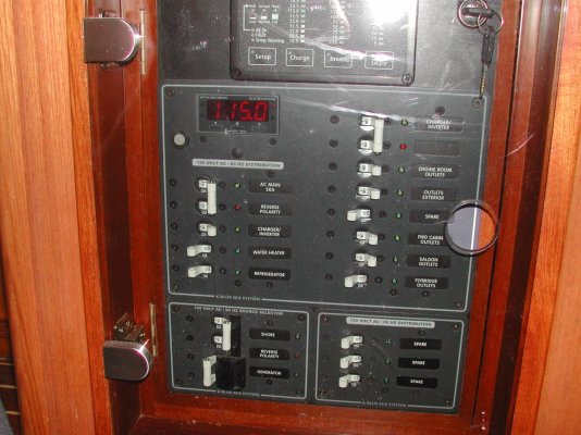
My AC panel has the slider that only allows for either shore power or gen-set power to be on line at any one time. As for inverter, anytime shore power or gen-set power are supplying the AC bus and “Invert” is selected, the inverter indicator light will blink indicating that the inverter will come on line when the other source of AC power is removed. Also, high draw items such as the electric water heater are not on the inverter powered circuit. This configuration must be fairly standard I would think.

Steve
 

Attachments

  • DSCN0124.jpg
    DSCN0124.jpg
    168.1 KB · Views: 142
Last edited:
My inverter has to be manually switched to work on the panel. But someone just suggested a Blue Seas 3 way switch that I couldn't find that I believe will solve my problem. I would love to find a dual pole breaker like yours that has 3 breakers with the sliders. I have seen them, just can't find one. I suppose I could build one myself in a 6 position panel. Thanks.
 
Would this work for you?
 

Attachments

  • Blue seas.jpg
    Blue seas.jpg
    179.3 KB · Views: 167
The Blue Seas switch will work. I couldn't find it. I do really like the panel tomas posted. My main electrical panel was made by Paneltronics and I have an email off to them now. The problem if they make it up, is that it takes them a long time. So the Blue Seas switch will probably do. Thanks.
 
If you are interested in buying Paneltronics product, check go2marine.com for price. I found their prices substantially lower than dealing direct with Paneltronics. Delivery time was the same, actually dealt direct with Paneltronics re: panel specs and manufacture.
 
My boat is only 30 amp, so it was an easy home-made solution. I have separate inverter fed receptacles so I don't have to worry about backfeeding that would make a male inlet hot.
One More Time Around: Transfer Switch
 
If you are interested in buying Paneltronics product, check go2marine.com for price. I found their prices substantially lower than dealing direct with Paneltronics. Delivery time was the same, actually dealt direct with Paneltronics re: panel specs and manufacture.

Yep, When I bought my main panel, Paneltronics worked with me to build it and processed the sale through go2marine.
 
The rotary switch by itself is available in 32A and 65A Off + 3 positions from Blue Seas. The 32A is PN 9010, check www.PKYS.com, Peter Kennedy Yacht Services.
 
Remember this is a bit harder than it seems as the ground from the dock must be carries aboard , but the noisemaker and inverter will have the neutral and ground joined .

I would use a simple home style switch , and hook the inverter to a relay as used for load shedding.

A 240 style switch is the most common.

Any power , pole or noisemaker , the inverter could not be powered.

KISS

For those with a low budget that can not afford a failure , the true KISS setup is an internal 240V 4 wire 50A PLUG , hooked to the boats dist system.

Then a set of 240 sockets (under $10 ea) would be wired to the power pole , the noisemaker and the inverter.

The system desired to power the boat is simply plugged into.

About $50 and there can not be a cross connection , "ooops" meltdown.

KISS is easy to troubleshoot , repair and have spares for.
 
Last edited:
A simple system would be to have the AC outlets and microwave always fed by the inverter (if on), no switches. The hot-water heater, water-maker, charger and other high AC loads which aren't normally fed by an inverter, have those circuits fed by either shore or generator.
 
On CF, I see you have already ordered your panel, but take a look at these:

Switch, AC 120VAC 30A OFF +3 - PN 9010 - Blue Sea Systems

Switch, AC 240VAC 65A OFF +3 - PN 9077 - Blue Sea Systems

I have the same inverter and generator that you do, and while I don't have two panels, I do have two legs of the AC panel I will need to feed. The 9077 switch is what I was going to use to solve the problem when I got around to wiring the inverter to the panel.

Here are the Defender link to the 9077:

http://www.defender.com/product.jsp?path=-1|328|303333|1330042&id=1329874
 
Searching on "rotary" at Defender results in 3 applicable 3-way switches.
 
Remember this is a bit harder than it seems as the ground from the dock must be carries aboard , but the noisemaker and inverter will have the neutral and ground joined ..

Yes, the shore power ground will have to be disconnected when the inverter or genset are being used.

Make sure you undestand how to do this correctly and safely before you start the project.
 
The Blue Seas 3 position took some searching to ultimately find until Tom posted. It looks like I will use two switches. The 3 way will connect the inverter, generator and shore power to the main panel. I have a 2 position switch now, which will connect the Air conditioning panel to shore power and the genset. So I think the issue is resolved. The generator will be delivered on Friday and then the real fun begins. the first thing will be to wrestle 200 lbs of generator into the engine compartment. Since this isn't a working marina we will indeed wrestle it into place. Thanks for the suggestions. Chuck
 
The neutral/green ground connecton problem will be handled as long as the switches/breakers you use break the neutral and hot. The green grounds can all go to one buss without any problem.
 
The neutral/green ground connecton problem will be handled as long as the switches/breakers you use break the neutral and hot. The green grounds can all go to one buss without any problem.

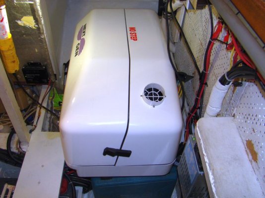
Yep, no problem with that. The transfer switches do break both the hot and neutral. The generator has arrived and we did indeed wrestle it into the engine compartment by hand. now the real fun begins. The second transfer switch has arrived and the pieces are all coming together. We will do a posting on our Beach House blog on the installation. Thanks for all your input.


generator sound shield.jpg
 
The neutral/green ground connecton problem will be handled as long as the switches/breakers you use break the neutral and hot. The green grounds can all go to one buss without any problem.
Not so. The ground must connect to the neutral at only one place, that being the point of origin. When on shore power, that is the service entrance at the marina. When on inverter or genset power, that is at the genset or inverter.

If you don't break the ground connection to shorepower when you switch to genset or inverter power, you will have two ground connections, one on your boat and one at the marina service entrance.

Yout lights and everything on the boat wll still work, so you think it's fine, but it's not. You can have current flowing in the ground circuit that shouldn't be. This could cause problems on your boat or other boats at the marina.

Check with an experienced marine electrician or look it up in the code book.
 
Think you can draw this out? I am not sure I understand.
 
are you saying the ground must also be switched?

On my system, the inverter has an automatic transfer switch that senses shore or generator power. It then passes that current through by passing the inverter. The sub panel for the inverter powered circuits does not connect to the neutral buss with the main panel. The neutral connects back to the inverter. The safety ground to the inverter serves as the ground. It carries through a large 2 AWG wire connected to the DC ground bus. This completely isolates the inverter and main panel circuits.
 
Last edited:
Back
Top Bottom