Saloon Stereo

The friendliest place on the web for anyone who enjoys boating.
If you have answers, please help by responding to the unanswered posts.
Joined
Feb 16, 2022
Messages
862
Vessel Name
Dream Catcher
Vessel Make
1979 Island Gypsy 44 Flush Aft Deck
Now that the TV has a place, time for the audio -:)

I replaced the flybridge stereo last year and happy with the results. Went with the same Kicker (gauge style, 3 inch hole) head unit I used before. Saloon stereo was non-op and while going through the wiring for the replacement I think I found the problem. One speaker wire shorted and blew the receiver which was a Sony home unit with 8 tiny speakers, 4 in the saloon, 2 in forward cabin and 2 in aft stateroom.

Replaced the 4 saloon speakers with Cambridge Audio Minx 22 and added the much needed subwoofer. Made up this custom panel to contain the head, switches for the cabin amp and the subwoofer and an aux switch so I can input from any outside source or select the TV output.

53526109929_62f7128ac6_b.jpg


That Alpine powered sub just fits in there sweet eh?

Next trip will be to mark the speaker leads and fix the bad wire and install the mating connectors so everything on that front panel can be unplugged easy for service.
 
It was a good day of checking wires. Some confusion after I started debugging the twisted wires and what I knew yesterday didn't work anymore.

The good news is I found all the individual speaker wires and only need to run 1 four conductor cable from the stereo box to the switch. I also found 6 wires not connected to anything. Suspect one of the PO's ran wires up to the fly and only had 1 switch box for the whole shebang. It did have 2 source inputs and 7 speaker outs, it's there on the counter.

The new system will be much easier. One head unit with a 4 channel amp and another 4 channel amp connected to the pre-outs. Eight speakers connected to 8 amplifiers. The head amps will run the fore and aft cabins and the aux amp will run the saloon. Fore and aft cabins will have speaker disconnect switches and the saloon will run with the aux amplifier and the subwoofer.

Yeah subwoofer...not really, it's just an 8 incher, but it will fill the lows which are not coming from the 2 inch minx's. Cross at 120 Hz.

Yeah, not ideal, but hey, it's a boat right - :)
 
Last edited:
  • Like
Reactions: PNW
Im sure it sounds great. I put a Fusion stereo in mine a while back and it sounds great. One of my favorite things to do in life is to go to the boat, put on some good music and work on the boat.
 
Today I got the ferrules installed on the switch box wiring for the fore and aft cabins and started on the Molex pins for the Saloon. Got the Molex mates on the head and amp connections, still need to run a 4 conductor to the switch box and then I can close up that big hole.

Instead of a panel with 8 switches on it there will be 2 push buttons, front cabin on/off and rear cabin on/off. The saloon will not be active unless the cabin amp is on. The Alpine has it's own on/off switch.

So will be possible to run saloon, fore and aft cabins alone or in any combination w/o much confusion.
 
Delays have been caused by the inability to remove a plywood under seat panel to get the power source. I finally cut out the wood and will replace with a hinged access. I wasn't going to try and run the whole stereo off the mid DC circuit, so I needed access to run a new circuit and I also need to replace the old inverter with a new unit.

I just made up the new panel with full piano hinge and now will be able to proceed. The new inverter/charger is needed to service the new LiFePO4 batteries that will replace the old 4D lead acid's made in 2017 and on their last legs.

Yeah, one project always leads to another and this has been on the books for a while. Now got everything opened up, old inverter out, new inverter in, buss bars to tap the house batts for (2) 10g runs to the stereo box and feed the new inverter.

The topside plan is clear now and when I get the inverter swap and the wiring in I can button up the stereo - :)
 
Progress, new hinged seat panel installed.

53560342186_73449771d1_o.jpg


Works great, sat on it the the whole time I removed the old inverter/charger, a Freedom 458 2KW modified sine that weighs 50 pounds and hummed so loud it was barely better than the generator. These things must be popular, still being made.

Here's a couple pics of the new speakers forward saloon with the new barometer and clock that replaced a couple of speakers that were not connected to anything.

53560669264_84f3afb981_o.jpg


53560782505_90930be441_o.jpg


Next trip will be bring in the new stuff, buss bars, terminal blocks, DC and AC breakers and 2/0 cable. So the stereo project also includes the inverter swap and proper protection for the new unit that wasn't there before as well as a little pretty up - :)
 
The new inverter/charger home;

53564217008_c94c0ca464_b.jpg


The two 2/0 g cables will be shortened and fixed to 2 buss bars on the floor. Two 10g runs off the small screws on the bars to the stereo and two 2/0 off the other fat studs on the other side of the bars to the inverter with the 250A breaker in the positive line.

The two smaller (red and black) cables are the 120 vac feed to the inverter that were not connected to the old one. It operated only as an inverter and not a charger as there is a separate charger in the engine room for the house batts. These 4g lines will be properly connected to a terminal strip on the back wall so 10g wires can be connected to the input of the new unit via a 30A breaker-disconnect installed on the outside of the seating frame.

The frame ground wire on the old unit is insufficient and will be replaced with a proper 8g wire.

Yeah, these old boats...lotta fixing and one project always leadsto another eh?
 
Progress.

The 2/0 DC has been routed to the 2 buss bars with the positive going through the 250A breaker/disconnect, verified operational.

The AC feed is hooked to the terminal block and operational.

Next is to cable over to another terminal block via some 4g I found in the closet. Might as well make use of it and it will shorten the 10g runs to the stereo box. After I get that in I'll be able to get 12 VDC into the stereo box and can get this project done as well as the new inverter/charger.
 
Getting closer, got the new circuit run to the stereo cabinet so I can get that part done and cleaned up and put away so the rest can begin.

The rest will be a lot of time in the engine room and it will be nice to have warmer weather for that. I have a portable heater in the saloon, but no room for that below and it's 55 degrees down there.
 
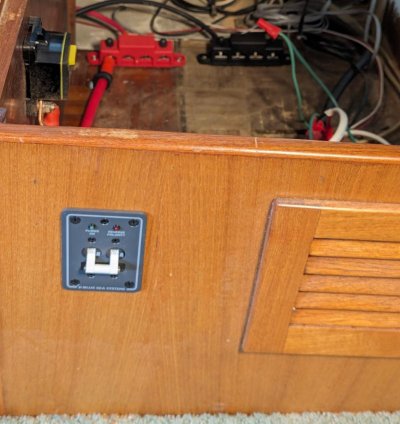
Got the 30A AC breaker installed. While testing all this circuitry I found there was no way to turn off the AC input to the inverter. If connected to shore power, always hot even if I switched to generator on the panel.

Blue inverter breakera1.jpg

Since this should be breaker protected on it's own circuit, another thing I had to fix. Went in pretty easy, used my saber saw and an 1/8" drill to cut the hole. A double layer of masking tape protected the nice wood - :)

Next trip out should have the stereo making music!
 
Last edited:
  • Like
Reactions: PNW
I should be on the boat now hooking up the stereo but alas, a flat tire. Tried to get it fixed at shop, but all busy. Found it sitting on the rim this morning. Pumped it to 35 psi and it was down to 30 in a half hour.

Put a can of flat fix in it and it's still leaking, but not as fast. Still not going to drive 40 miles on high speed country roads in this condition.

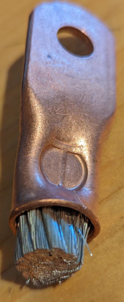
Back to the point, a recommend on a crimp tool that I've been giving lots of use lately. Still very heavy, but small size as these things go and no dies to worry about and you also don't need to worry about fit. So far I've crimped 6g, 4g and 2/0 and all worked well. Here's a pic of a 2/0 crimp
 

Attachments

  • Crimp on 00a.jpg
    Crimp on 00a.jpg
    140.4 KB · Views: 8
The deed is done! Spent 5 hours on the yacht today getting this baby buttoned up.

53593586132_af59e496d5_c.jpg


A few more strips, crimps and screws. But a big part was the blending. Speakers have not much below 120 Hz. Started with the sub at 120 and the head at 120. Not as smooth as I like. The magic happened when I set the speaks to 80. The blend was much better, smooth as silk. All the bass seemed to come from the impossibly small speakers. The Cambridge Minx 22's are very good as they should be for a buck and a half each. No stranger to Cambridge, I use them for the home theater.

Looks good and sounds good;

53594782819_1d7ae11610_c.jpg


I spent a half hour just listening. The sub was much better secured to the wall. The top (green) switch controls the amp and the red does the sub. The aux switch just below will input via 3.5 mm jack on the input panel which also does the USB and switch to the AV inputs already run from the TV mount. All the other circles are just vents. But the middle one is right in front of the amp to allow access to the switches and level controls as well as the mic input for when I run the DSP setup and get it all equalized and time aligned.

Last but not least the switch box

53594459861_60bf574942_c.jpg


No more confusing array of switches that do nothing, a push button to turn fore cabin and aft cabin on/off and the middle toggle turns on the head. I also have the new inverter bluetooth remote mounted so that is ready also.

The inverter install is next followed by isolation in the engine room and the move to 600AH of LiFePO4. Getting ready to cruise - :)
 
  • Like
Reactions: PNW
Got the AC output from the inverter hooked up and enjoyed the stereo while I did that. Then stereo off to disconnect the hi-amp DC and I cabled up the 2/0 to the DC input. Next will be turn off the shore power and get the AC input side hooked up.
 
Nicely done and well-documented! The Trawler we just bought has a dead stereo so I'll be on this train eventually as well. Cheers
 
Thanks!

I love AV projects and I don't like stuff on the boat that doesn't work, needs repair or how you say "what was he thinking"...
 
  • Like
Reactions: PNW
Today I got the inverter / charger installed and verified. Bluetooth remote got updated firmware and verified working. Inverter powers AC loads with batteries and charges batteries when AC powered. It all works as advertised - :)

The Bluetooth is much easier to use than the button interface and I set charge current to 30A max on set AGM battery. When switched on charge displayed as 29.5 bulk. Cool. Voltage came up very quickly as I expected it would on these old worn out batteries.

But the cool thing is it's verified operational! Now on to the lithium swap - :)
 
  • Like
Reactions: PNW
Yesterday I really finished up the stereo. Replaced the front and aft cabin speakers too. New speaks are not as good as the saloon speaks but hey they cost $50/pair instead of $150/each. They do sound much better than the old ones vintage unknown. When I did the compare it was shrill as compared to smooth.

Also changed out the DC thermal breaker to a Blue Sea 300A switch with a 250 A fuse. Heard some upsetting stuff about excessive voltage drop with the thermal breakers. Also wanted to be able to control the thing from the outside as opposed to lifting the seat cushion and under panel so here is the new setup, AC and DC disconnect side by side;

53674169589_d9ed71f872_c.jpg


And here is the completed install;

53674169584_2bedaa2f82_c.jpg


Now down to the engine room to begin the battery isolation / replacement thing with new chargers and isolators - :)
 
We have a Sonos system at home and are very happy with it. Until now, we've made do with various Bose bluetooth speakers but am thinking about moving to the Sonos Move 2 speakers but will likely skip the sub woofer. A little too much for use in the marina and waaay too much when anchored out.
 
Not to be over critical, but if the inverter/charger is a 3kw model (it's hard to tell) you would need a 350 Amp fuse to allow it to run flat out for any reasonable amount of time. This fuse must be at the battery not mounted on the battery switch and will likely need to be a Class T or better fuse (with an AIC of 20,000 Amps) especially should you change to LFP as planned. Further, the inverter's existing 2/0 supply conductors (which have an Ampacity of 330 Amps if not in the E.R.) are limited in length to only 14' total, should you want to limit Voltage drop to 3% (0.36 V) while carrying 300 Amps. I would change those to 4/0 conductors and limit their length to about 10' total, which is likely what Xantrex recommends in their manual.

Although there might have been some existing 2 conductor cable (black & red) in place that was handy, but adding more and placing both in the ac circuit is less than acceptable and could be dangerous in the future.
I would change these conductors to the appropriate size of 3 conductor (black white green) cable and route it correctly. Pay attention to the grounding (green) conductor, it is important.

It's your boat, don't put it or any person in peril.
 
Thanks for the review.

It is a 3 KW unit but I have it set maxed at 2.5 KW. The AC in and out is 10g with a 10g green ground wire which is good for 30A. Yeah, the colors are DC style, but all the connections are good and solid and all grounds have been verified. GFCI has been verified.
 
Yeah, by way of bluetooth, wifi or hocus pocus you can set the input current to the inverter at a reduced level. By the same method the next owner can increase it back to the max. What is wrong with installing the inverter so that there is no traps set?

LFP batteries can deliver an enormous amount of current, you need to wire and fuse the system correctly to be idiot proof and safe.

In the dc world, a black conductor is (or was) dc negative, which is harmless. In the ac world (which is what you are using the conductors for) a black conductor is the ungrounded (hot) lethal conductor.

Again, it is your boat.
 
Yeah, that's the way I found it...

Glad I hit the wires with a meter before proceeding - :)

The (2) 300 AH LiFePo4 batteries have a 200A UL approved BMS on each of them. I plan to use the same 250A fuses on each battery right on the post. They appear rated for 10000 A disconnect.
 

Latest posts

Back
Top Bottom