If you want to connect your existing alternators to LiFePO4 batteries you are going to need some form of controller that can be programmed.
You will need it for two reasons:
There are a bunch of good points here, but also potentially misleading without more context
1. A LiFePO4 battery can take a max capacity charge of the alternator until it is full and then it will shut down all of a sudden.
This needs clarification. When LFP batteries reach full charge the voltage rises rapidly and you need to stop charging current before the cells go over voltage. So in that sense the alternator output will reduce/stop quickly.
It’s also true that if charging drives the batteries over voltage, the BMS should disconnect the batteries. If this sort of a “shutdown” is occurring, then there is a problem with the system, and the charging parameters in particular. A BMS shutdown is a fault condition, and should never happen in normal operation.
Charging at full capacity can mean the alternator can overheat, so you will have to limit the max charge of the alternator to around 80 %. That way it won't overheat and your battery will charge at a high level.
That’s one way to do it. Alternately, most good external regulators have alternator temp sensors, and the regulator will limit output to not exceed a safe operating temp for the alternator.
2. When the LiFePO4 batteries are full the alternator needs to stop charging, which means it needs to be cut out of the loop. If you don't do that you will get a power surge in your electrical system, potentially frying a lot of equipment. There are regulators such as Wakespeed WS500, but there are also others.
When the batteries are full, then regulator need to reduce current, and in time switch to a lower float voltage. There is no need to disconnect it, if that’s what’s meant by “cutting it out of the loop”. If fact, an abrupt disconnect is exactly what creates a possible surge. Any regulator will reduce current in a controlled manner to maintain the programmed voltages. It’s what they do in life.
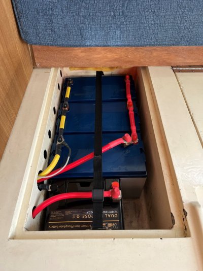
Reason for the cables having to be at exactly the same length is that otherwise the battery with the longer cables is not going to be used as much or even at all. The max difference in cable length is less than 1 cm.
Also, before you connect the terminals, clean them all very well, make sure there is no grease or sweat on them. That would influence the connection and cause major problems later on.
Another important item is the battery balancer. Depending on which BMS you have (and whether the batteries have an internal balancer) you will need to allow time for balancing.
A LiFePO4 battery will first charge, but the individual cells won't be balanced. After the battery is full the balancing will start. That can take quite a while and if you would start discharging at that time the battery cannot deliver max capacity.
In what way wouldn’t the batteries be able to deliver full capacity? They could certainly deliver full current, and do so for all or nearly all of the SOC range. I suspect what you mean is that with one or more cells out of balance, the battery may appear full discharged when the lowest cells go flat even though there is charge left in other cells. This is true, but unless the cells are massively out of balance, it’s immaterial.
A battery with an internal BMS will have less problems with balancing than a set of batteries which is balanced by one BMS only.
There are lots of different balancing circuits with varying levels of performance, but I don’t think there is any inherent performance advantage in internal vs external. So i don’t think it’s a good basis for judging the performance of a balancer.
Changing to LiFePO4 does have a lot of consequences, but in the end it is definitely worth it.
Totally agree.