Isolation transformer reverse inputs

The friendliest place on the web for anyone who enjoys boating.
If you have answers, please help by responding to the unanswered posts.

davidla

Veteran Member
Joined
Jul 9, 2023
Messages
55
Vessel Name
Shady Lady
Vessel Make
Main ship Trawler 400
Hi
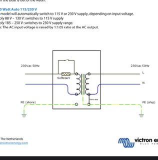
This question is more for those using the Mainship in locations such as Australia and Europe and pertains to the Mainship 400 and 240 volt use of the installed Charles Industries transformer.
I am wondering if anyone has reversed the input and output in these devices to create a proper isolation transformer in the 2 wire (live and neutral) 240volt scenario?
Currently both my safety ground for fwd and aft shore supply are connected to boat ground and there is no galvanic isolator:banghead::banghead:.
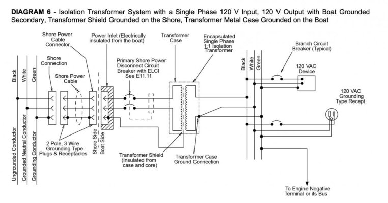
I figure if you reverse them as is done in the US to boost 208v dock supplies, you can then ground the shore neutral to shore ground and the case. At the same time you can ground the boat ground to the shield and jumper a neutral.
Thoughts please.
 
In general, yes, you can run a transformer in either direction. But the shield should always be connected to the shore ground, and the case should be connected to the boat's ground.


That said, I'm not following what you are proposing to do, or what problem is it intended to solve. Any chance of a sketch of current and proposed wiring?
 
Thanks for your reply. I am trying to achieve a similar configuration to that seen with the newest Victron iso Transformers. I'll see if I can upload a screen shot of how they are wired.

The Victron example wiring below shows boat ground to shield and when you jumper it to the neutral then you get the desired zero volts on neutral and 240 on the hot. T
he way the US system works generally is you have 2 110 volt hot wires then you bond one at the AC panel and thus the other assumes 240v.

I would be unconcerned if the ground from shore was only grounded to the case as it is hidden behind wood panelling and is hardly "touchable" In the event the hot chafes through its clamp and contacts the case then the shore side RCD will trip.
I don't have the capacity to draw something for the existing layout atm. I think it is probably pretty much factory spec except all safety grounds are bonded together.
 

Attachments

  • IMG_0191.jpeg
    IMG_0191.jpeg
    19.2 KB · Views: 82
Let's start with what your shore cord is (30A 120V, 50A 120V, 50A 120/240V)? And what power is available on your boat (single 120V service, separate 120V services, 120/240V split phase service)?


Victron's iso transform is strictly single phase, so 230V outside North America, and 120V in NA. It's not suitable for NA split phase power.


I have never looked at it closely, but the grounding of the shield and case is exactly opposite what's require by ABYC. I don't know if that's what's required in Europe, or if it's a drawing error. Regardless, it's an interesting catch.
 
The power onboard and from shore is 240v 15amp single phase, including output from the generator (higher amperage). The Victron single phase design equivalent is all I think I need. We have a hot and neutral into and out of any transformer. The ground wire is the only outlier. When you connect the neutral in our case, it does not attach to the centre tap but in one of the primary windings on each side (in and out). ABYC requirements are separate and of no consideration in this case.

We do have to bond the neutral to the ground at the source output (this is required) and an Isolation Transformer is a source. I believe the ABYC does require US boats to be able to trip the ELCI (what we call an RCD) at the shore input for a transformer and I don't know how this would be achieved if the safety ground is only connected to the shield of the transformer???

The way the Charles onboard my boat is currently configured has the output GND connected to the case ground. The SH is connected to the shore input safety ground. If the input hot were to chafe through to the case it would cause a path to ground through the case, to the safety ground on the boat side and then its only path back to the source (shore supply) would be through the water. (albeit the shore side RCD should trip with the imbalance in the hot and neutral)
This is, I suspect, why the PO connected all grounds together, but did not install a galvanic Isolator. I would prefer to use the Iso transformer exactly as it is designed and thus isolate the grounds. I think I will try it in both configurations and check all aspects for safety on the input.
Thanks for your help.
 
Ah, Syndney Aus, not BC. So 230V single phase both on shore and one the boat. Got it.


Definitely do not connect the boat and shore grounds as that defeats the whole purpose of the isolation transformers.


The use of the shield ground on the boat side vs shore side is a bit of a mystery. Both ISO and ABYC call for using the shield for the shore-side ground, and the case for the boat-side ground. The rational may be related to tripping shore side RCDs, as you describe. None of these protective measures is 100%, and I expect there are tradeoffs no matter how you do it. I believe the intend of the standards is that the shore ground protects against faults in the shore cord and inlet through to the onboard breaker/RCD. I don't know if ISO or something else is required in Aus, but it would be worth checking applicable regulations.


One way to look at this is that if you used a Galvanic Isolator, how would the two grounds be handled? The shore ground is connected exclusively to the isolator, which seems equivalent to connecting it to the shield with a transformer.


For reference, attached is the applicable ABYC diagram, which I believe says the same thing as ISO.
 

Attachments

  • diagram6.jpg
    diagram6.jpg
    89.2 KB · Views: 43
Back
Top Bottom